


4
8. Press the key.
9. Press the key until ‘DISP’ is displayed. Wait
10 seconds and cycle the control power using the On/Off
switch.
The chiller is now configured for minimum load valve control.
Test Minimum Load Relay Output — Use the Scroll-
ing Marquee display, the instructions given in the Controls,
Start-Up, Operation Service and Troubleshooting manual and
the Service Test mode to verify proper operation of the
solenoid(s) (illuminate the Service Test LED, enter the TEST
mode, enable the test request, ‘T.REQ’ and test outputs
‘HGB.A,’ ‘HGB.B’ and for 30RB210-300 only, ‘HGB.C.’
Once the outputs have been tested, the installation is complete.
Return the Enable/Off/Remote contact switch to the desired
position.
ENTER
ESCAPE
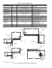
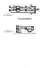
00PPN500000600A
TUBE ASSEMBLY
5/8 IN.
TUBING CLAMP
(TYPICAL)
BALL VALVE
SOLENOID VALVE
FIELD-
SUPPLIED
TUBING
BALL VALVE
SOLENOID VALVE
5/8 IN.
TUBING CLAMP
(TYPICAL)
CIRCUIT A
CIRCUIT B
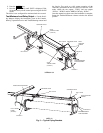
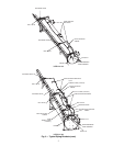
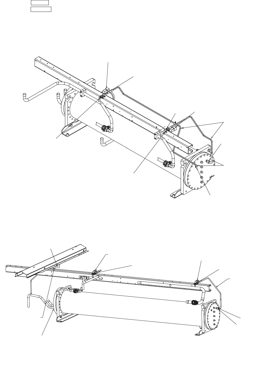
FIELD-SUPPLIED
TUBING
SOLENOID VALVE
SOLENOID VALVE
00PPN500000600A
TUBE ASSEMBLY
1/2 IN. TUBING
CLAMP
(TYPICAL)
BALL VALVE
BALL VALVE
TUBE SUPPORT BRACKET
CIRCUIT A
CIRCUIT B
30RB110
Fig. 5 — Typical Piping Brackets
30RB060-100