


Installing the Camera
The procedures for mounting the camera to the ceiling using the indoor dome housing are
described below.
Before installing the camera, set the IP address and other network information on the camera
using the "VB Initial Setting Tool".
For details on how to operate the "VB Initial Setting Tool", see VB-M40 Operation Guide.
If using an SD memory card, insert the SD memory card into the camera before installing (see
"Using an SD Memory Card" in VB-M40 Installation Guide).
Important
Once the camera is installed to the ceiling, to insert and remove the SD memory card, the camera must
be removed from the ceiling and the ceiling bracket dismounted.
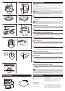
1
Determine an installation position for the camera and drill holes in the ceiling
Using the bundled template, line up the directon of the camera, determine the locations of the
backside ceiling bracket mounting holes (three) and the ceiling bracket holes, then drill the
holes into the ceiling.
Important
When mounting the indoor dome housing, be sure no shavings enter the dome.
2
Mount the camera to the ceiling bracket
Affix with four bundled fixing screw (M3).
3
Mount the dust cover to the ceiling bracket
Affix with three bundled fixing screw (M3).
4
Attach the backside ceiling brackets inside the ceiling
From the inside of the ceiling, insert the protrusions on the backside ceiling brackets through
the mounting holes drilled in step 1.
5
Temporarily tighten screws to the backside ceiling bracket
Temporarily tighten the three bundled ceiling bracket screws (M4) through the ceiling.
6
Secure the safety wire
Securely attach the safety wire to an anchor or structure. After securing the end of the safety
wire to the ceiling, secure the other end to the camera using the screw that is fastened to the
camera.
7
Connect the LAN cable to the camera through the wiring hole
If an AC adapter PA-V17 (optional) or external power supply is used, connect the power
connector to the camera. Connect cables to external device I/O terminals and audio input/
output terminals as necessary (see "Connecting the Camera" in
VB-M40
Installation Guide).
8
Mount the ceiling bracket on the ceiling
Position the ceiling bracket over the screws temporarily tightened in step 5, turn clockwise to
temporarily secure in place, and completely fasten the screws.
9
Attach the dome
Align the (O) mark on the dome with the (I) mark on the ceiling bracket, and turn clockwise
until the (I) mark on the dome aligns with the (I) mark on the ceiling bracket. This procedure
also aligns the ceiling bracket screw hole with the dome fixing screw hole.
10
Affix the dome
To prevent the dome from rotating, attach one dome fixing screw (M2).
11
Reboot the camera when the installation is complete
The camera position is initiated (see "Maintenance" in Chapter 4, "Setting Page" of the
VB-M40
Operation Guide).
Note
While the LED is on, light may reflect inside the dome and be captured on video. If this happens, set the
LED setting to [Off] (see “LED Setting” in VB-M40 Operation Guide).
9
8
6
4
23
5
7
10
Main Specifications
Model DR40-C-VB/DR40-S-VB
Type Clear type/smoked type
Network camera-mounting environments Temperature -10 to 50°C (14 to 122°F), humidity 5 to 85%RH
(non-condensing)
Dimensions (Φ x H) 204 (112: Dome) x 92 mm (8.03 (4.41: Dome) x 3.62 in)
*Including ceiling-embedded section: 176 mm (6.93 in) (H)
Weight Approx. 765 g (1.687 lb) (excluding camera)
Smoked (DR40-S-VB)
This dome is approximately 50% transparent.
Minimum subject illumination
Day Mode (color) :
0.8 lux (F1.6, Shutter Speed 1/30 sec., when Smart Shade Control is off)
0.2 lux (F1.6, Shutter Speed 1/8 sec., when Smart Shade Control is off)
0.06 lux (F1.6, Shutter Speed 1/8 sec., when Smart Shade Control is on)
Night Mode (monochrome) :
0.02 lux (F1.6, Shutter Speed 1/30 sec., when Smart Shade Control is off)
0.004 lux (F1.6, Shutter Speed 1/8 sec., when Smart Shade Control is off)
0.002 lux (F1.6, Shutter Speed 1/8 sec., when Smart Shade Control is on)
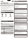
External Dimensions
DR40-C-VB/DR40-S-VB Backside ceiling bracket
204.0 mm (8.03 in)
164.0 mm (6.46 in)
112.0 mm (4.41 in)
84.0 mm
(3.31 in)
92.0 mm
(3.62 in)
11
Safety Wire
Secure to an
anchor or
structure
LAN cable
Ceiling
bracket
Backside
ceiling
bracket
Ceiling board
Dome
Camera
10.0 mm
(0.39 in)
7.0 mm (0.28 in)
Height
Bundled
screw
M3 x 3
Bundled
screw
M3 x 4
Bundled
screw
M4 x 3