


Part One
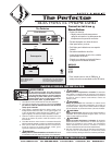
PLACEMENT: Read IMPORTANT INSTRUCTIONS for important safety requirements. For best results,
install heater beneath a cabinet in the toe kick area. Install the Perfectoe (Model UC) horizontally. Do not
install the UC heater in the floor. Headers and bracing are not necessary. Heater must be installed per the
directions indicated on the lid. See clearance requirements for additional placement instructions. Install
at least 6” from the inside corner and/or vertical adjacent surfaces.
CONTROLS: A thermostat is required. A Cadet electronic thermostat is recommended for ultimate control
and comfort. Optional single or double pole field mount thermostat kits are also available.
STEP 1 Turn the Electrical Power OFF
Turn the electrical power off at the electrical
panel board (circuit breaker or fuse box) and lock
or tag the panel board door to prevent someone
from turning on power while you are working
on the heater.
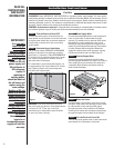
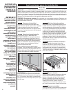
STEP 2 Determine Area of Installation
The UC Series heater REQUIRES A MINIMUM
distance of 6 inches from adjacent surfaces
(See Figure 1). However, Cadet RECOMMENDS
12 inches from all adjacent surfaces for longer
and cleaner performance. Heaters must be
spaced at least 3 feet apart.
For installation in an existing wall/cabinet, cut
a rough opening 14½ inches wide by 3½ inches
high. Opening must be 8½ inches deep and
6 inches from adjacent wall.
WARNING! Vinyl floor manufacturers warn
that some vinyl may discolor from temperatures
in excess of 110° F. See your vinyl floor
manufacturer for temperature specifications
for your vinyl floor covering.
STEP 5 Mount the Heater
Reinstall heater lid and attach using four screws
provided. Slide heater into opening. Fasten heater
to cabinet with screws (not provided) going
through the lower holes located on the flanges.
Fasten grill to heater with screws provided going
through the upper holes located on the flanges.
STEP 6 Turn the Electrical Power ON
Turn the electrical power back on at the electrical
panel board (circuit breaker or fuse box).
Figure 1
Installation
Instructions
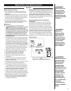
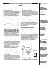
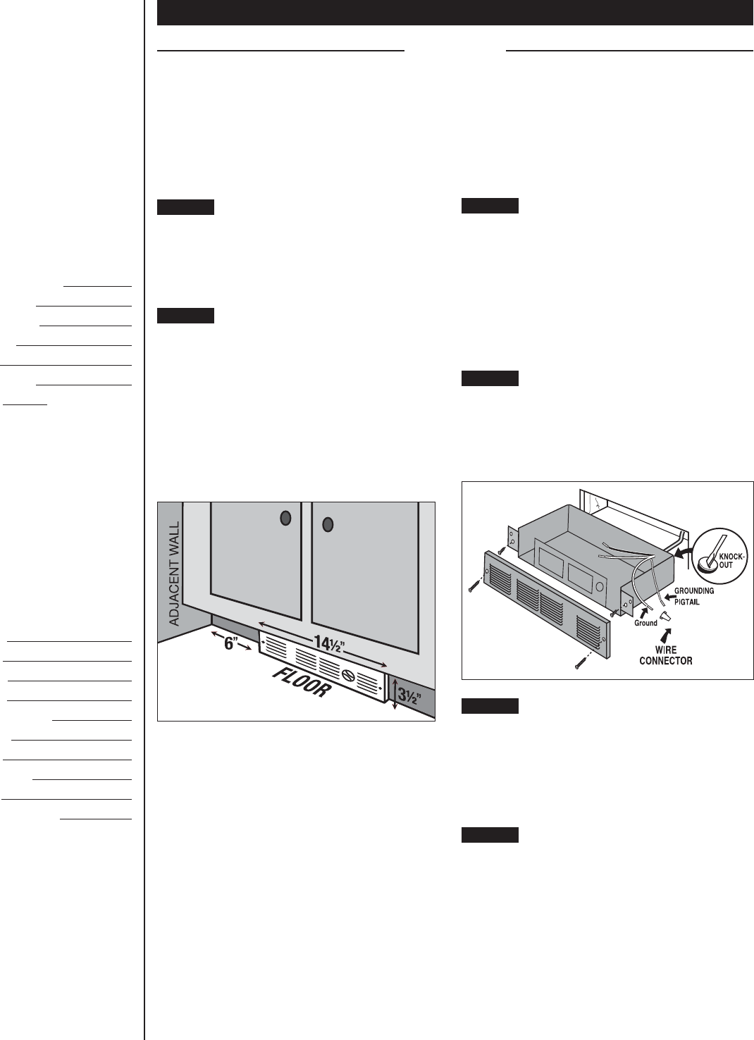
STEP 3 Route Supply Wires
For wall thermostat applications, route supply wire
from circuit breaker to thermostat to rough
opening. For models with an optional field mount
thermostat kit, route supply wire from circuit
breaker to rough opening. Allow enough wire to
extend 12 inches beyond the opening. Place heater
lid aside. Remove the knockout and attach the
supply wire with a strain relief connector, leaving
6 inches wire lead for later use (See Figure 2).
Figure 2
STEP 4 Connect Supply Wires
Connect the supply ground wire to the green
grounding pigtail provided (See Figure 2). Connect
each supply wire to one heater wire with wire
connectors. Note: All wire connections must be
made inside the heater.
READ ALL
INSTRUCTIONS
AND SAFETY
INFORMATION
IMPORTANT!
It is extremely
important that
you verify the
electrical supply
wires are the same
voltage as the
heater (i.e. 120 volt
heater to 120 volt
power supply and
240 volt heater to
240 volt power
supply). If
replacing an
existing heater,
check the labels of
the old heater and
replace using the
same voltage.
Hooking a 240 volt
heater to a 120 volt
power supply will
drastically reduce
the heater’s
output. Hooking a
120 volt heater to a
240 volt power
supply will destroy
the heater.
Connecting your
heater to an
incompatible power
supply will void the
warranty.
2