


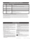
INSTALLATION INSTRUCTIONS
READ ALL
INSTRUCTIONS
AND SAFETY
INFORMATION.
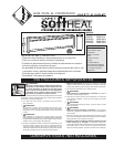
CAUTION - High
Temperature, Keep
Electrical Cords,
Drapes, And Other
Furnishings Away
From Heater
WARNING!
RISK OF ELECTRICAL
SHOCK. TURN OFF
ALL POWER AT THE
ELECTRICAL PANEL
BOARD SUPPLYING
POWER TO THE
HEATER BEFORE
DOING ANY
ELECTRICAL WIRING.
WARNING!
Risk of Fire.
Heater must be
kept clear of all
obstructions:
12” in front and above;
6” on both sides
minimum.
IMPORTANT!
It is extremely
important that you
verify the electrical
supply wires are the
same voltage
as the heater (i.e. 120
volt heater to 120 volt
power supply and
240 volt heater to
240 volt power
supply). If replacing
an existing heater,
check the labels of
the old heater and
replace using the
same voltage.
Hooking a 240 volt
heater to a 120 volt
power supply will
drastically reduce
the heater’s output.
Hooking a 120 volt
heater to a 240 volt
power supply will
destroy the heater.
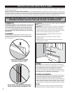
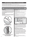
8. After confirming heater is level, fasten other end of
heater to wall stud with screw to wall.
SUPPLY
STUDS
FLOOR
FINISHED
WALL
Figure 1
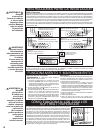
STEP 1: Mount Heater to Wall
1. Locate wall studs closest to supply wires and position
heater (See Figure 1). NOTE: Wire connection is from
left side only on standard models.
STEP 2: Wiring Provisions / Wiring
This heating unit is designed for permanent installation.
All wiring should be routed in compliance with the
National Electrical Code and all local codes, where
applicable. A maximum of No. 10 AWG wire may be
used with this heater. All wiring should be planned
and run before heating units are set in place.
Standard units are wired from left end of the heater
only. (See Figure 5 for internal heater wiring).
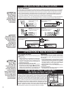
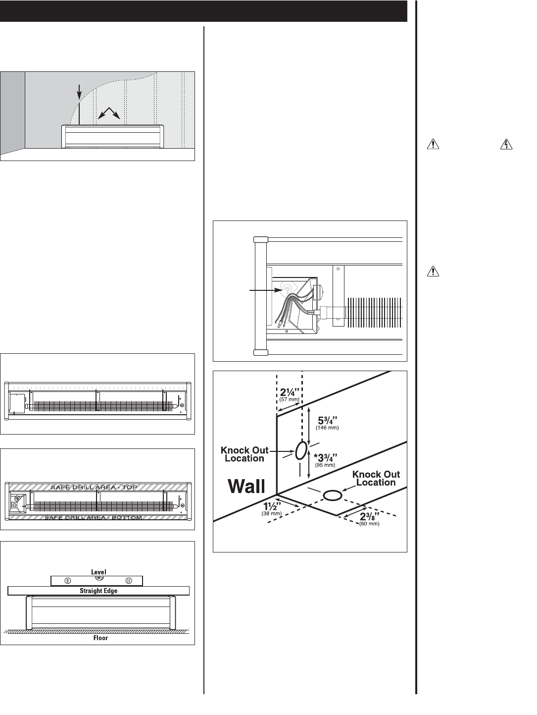
When wiring unit through rear, remove knock out and
place heater on wall. Mark knockout location on wall.
When running conduit or cable to unit through flooring
and knock out in bottom of wiring compartment,
measure 1-1/2” (38mm) from wall and 2” (51mm)
from left end of unit. Cut a 7/8” (22mm) hole in floor
centered on the measured location (See Figure 6).
Connect the grounding lead to the green ground
screw (provided), using a connector. (See Figure 5).
Protect electrical supply from kinks, sharp objects, oil,
grease, hot surfaces or chemicals.
*Distance measured from finished floor surface.
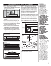
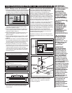
2. Carefully remove front cover from heater by lifting
cover up from the bottom, and then outwards.
Set aside.
3. Remove wiring compartment cover, held by one
screw, from side you wish to wire. (Figure 2).
4. Remove slotted knockout closest to the supply
wires and install a strain relief connector.
5. Pull supply wires through the connector and secure,
leaving 6 inch wire leads for later use.
6. NOTE: If you will be installing a heater mounted
EBKN thermostat, you should do so now before
mounting your baseboard to the wall. See your
EBKN thermostat Owner’s Guide for instructions.
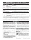
7. Position the heater and fasten one end of heater
to wall stud with screw in safe drill area as shown
in Figure 3. Before fastening to wall stud at other
end, place level across top of heater and make sure
heater is level. (Figure 4).
Figure 5
Figure 6
Figure 4
Checking with level
Figure 2
Left-end wiring shown
Figure 3
Drill areas
Left-end wiring shown
Left-end wiring (standard)
Ground
Screw
3