Installation Instructions
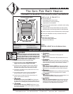
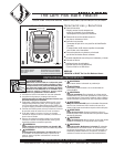
WARNING
Turn the electrical
power off at the
electrical panel
board (circuit
breaker or fuse box)
and lock or tag the
panel board door
to prevent someone
from turning on
power while you
are working on the
heater. Failure to
do so could result
in serious electrical
shock, burns, or
possible death.
WARNING
Risk of Electrical
Shock. Connect
grounding lead to
grounding screw
provided. Keep all
f
oreign objects out
o
f heater.
WARNING
Risk of Fire.
Heater must be
kept clear of all
obstructions: a
minimum of 3’ in
front; 6” on both
sides and above.
Heater must be
kept clean of lint,
dirt and debris.
STEP 1
Part Two
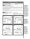
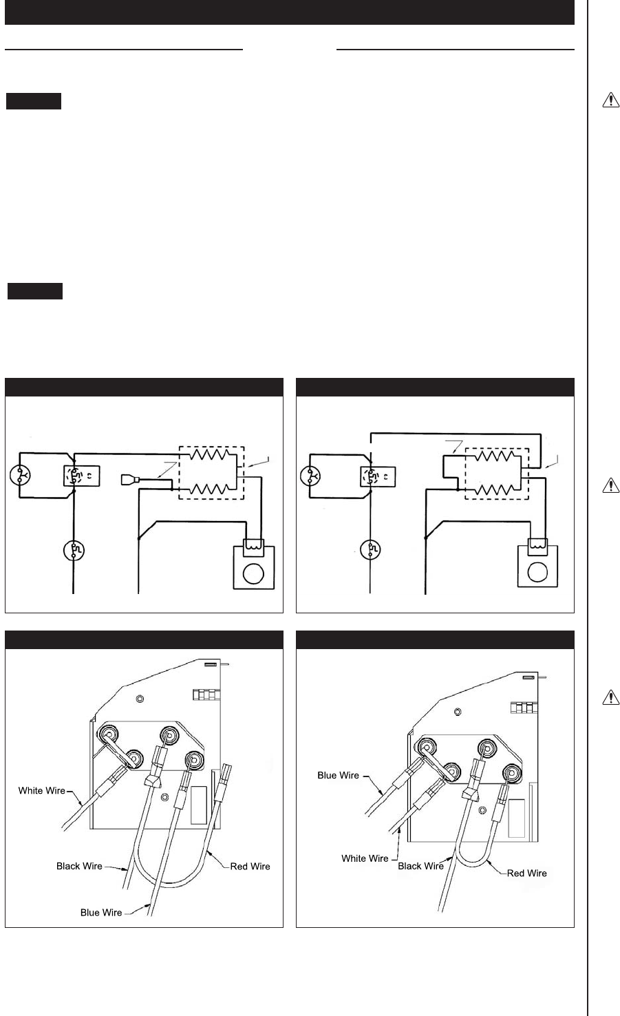
Multi-Volt Element Wiring Configuration: Refer to Figures 5, 6, 7 and 8 for desired voltage.
TIMER
3 6
1 4
L1 L2
HEATING ELEMENT
MOTOR
JUMPER WITH
INSULATED Q. D.
3 6
1 4
L1 L2
MOTOR
JUMPER WITH
INSULATED Q. D.
SPARE
TERMINAL
ON ELEMENT
SHORTING
BAR
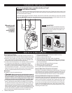
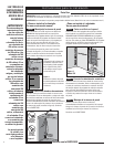
Heater must be connected to a GFCI protected branch circuit.
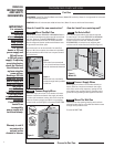
Before installing the heater, it is extremely important you verify the heater is configured for the correct supply
voltage. The Com-Pak Bathroom Heater is configured for 240-Volt operation by default. For 120-Volt installation
you must reconfigure the heater wiring. Installing the heater without configuring for the correct voltage will
destroy the heater and void your warranty.
How to determine the supply voltage:
If replacing an existing heater, check the labels of the old heater and replace using same voltage. For new
construction, heater wires must be configure
d to the same voltage as the supply wires. If you need assistance,
consult a qualified electrician.
Determine Supply Voltage
STEP 2
Select Proper Heater Voltage
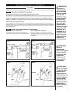
For 240-Volt configuration:
The Com-Pak Bathroom Heater is configured for
240-Volt operation by default.
240 VOLT POWER SUPPLY 120 VOLT POWER SUPPLY
CORRECT 240 VOLT CONFIGURATION CORRECT 120 VOLT CONFIGURATION
For 120-Volt Configuration:
To configure heater for 120-Volt, disconnect the blue
wire from terminal D and connect it to terminal A.
Then connect the loose red wire to terminal D.
A
B
C
D
A
B
C
D
THERMOSTAT
A
B
D
C
3
Figure 5
MANUAL
RESET
HIGH
TEMPERATURE
LIMIT
MANUAL
RESET
HIGH
TEMPERATURE
LIMIT
Figure 6
Figure 7
Figure 8
THERMOSTAT
TIMER
HEATING ELEMENT
SPARE
TERMINAL
ON
ELEMENT
SHORTING
BAR
D
A
C
B


