MULTIPLE BASEBOARD WIRING. 240V SUPPLY ONLY
(See Figure 14)
1. Left side wiring: disconnect factory connector A. Right
side wiring: disconnect factory connector B.
2. Connect one wire from each heater to one supply wire.
3. Connect remaining wire from each heater to the
remaining supply wire.
4. Connect supply ground wire to both ground leads.
Note: Field wiring is not provided
Multiple Baseboard Wiring - Optional
Follow the instructions below if you are wiring more than one heater in parallel on same circuit.
If you are wiring multiple baseboards to one control, it is recommended that you use one control per room.
B
Do not disconnect
Ground
Field Wiring
Heater Wires
To Wall Thermostat
A
Baseboard Heater
Right Side
Baseboard Heater
Left Side
Baseboard wiring with a wall thermostat - Optional
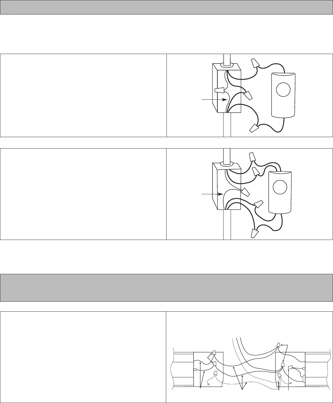
SINGLE POLE WALL THERMOSTAT
1. Route supply wires to the thermostat wiring box (if not
already present).
2. Connect one supply wire to one thermostat wire (typically
marked L1).
3. Route remaining thermostat wire (typically marked T1)
to the baseboard heater.
4. Route remaining supply and ground wire to the baseboard
heater.
5. Follow installation instructions for mounting and wiring
baseboard heater.
DOUBLE POLE WALL THERMOSTAT
1. Route supply wires to the thermostat wiring box (if not
already present).
2. Connect one supply wire to one thermostat wire (typically
marked L1).
3. Connect remaining supply wire to other thermostat wire
(typically marked L2).
4. Route remaining thermostat wires (typically marked T1
and T2) to the baseboard heater.
5. Route ground wire to the baseboard heater.
6. Follow installation instructions for mounting and wiring
baseboard heater.
Refer to the wiring diagram below that corresponds to your thermostat application. Note: Wiring diagrams are for reference only.
See wall thermostat instructions included with your thermostat for your specific application.
For instructions on wiring using an in-built thermostat, see Cadet BTF1, BTF2 and SBFT2 Installation Instructions
Figure 12
Figure 13
Figure 14
STANDARD
BASEBOARDS
SHOWN
To Supply
T
hermostat
w
iring box
T
hermostat
w
iring box
Ground
Single Pole
Thermostat
D
ouble Pole
T
hermostat
L1
T
1
L2
T2
L
1
T1
To Heater
To Supply
To Heater
5
G
round


