


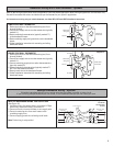
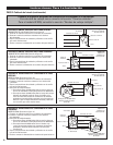
Figure 9
Left Side
Wiring Shown
Figure 8
Right Side
Wiring Shown
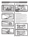
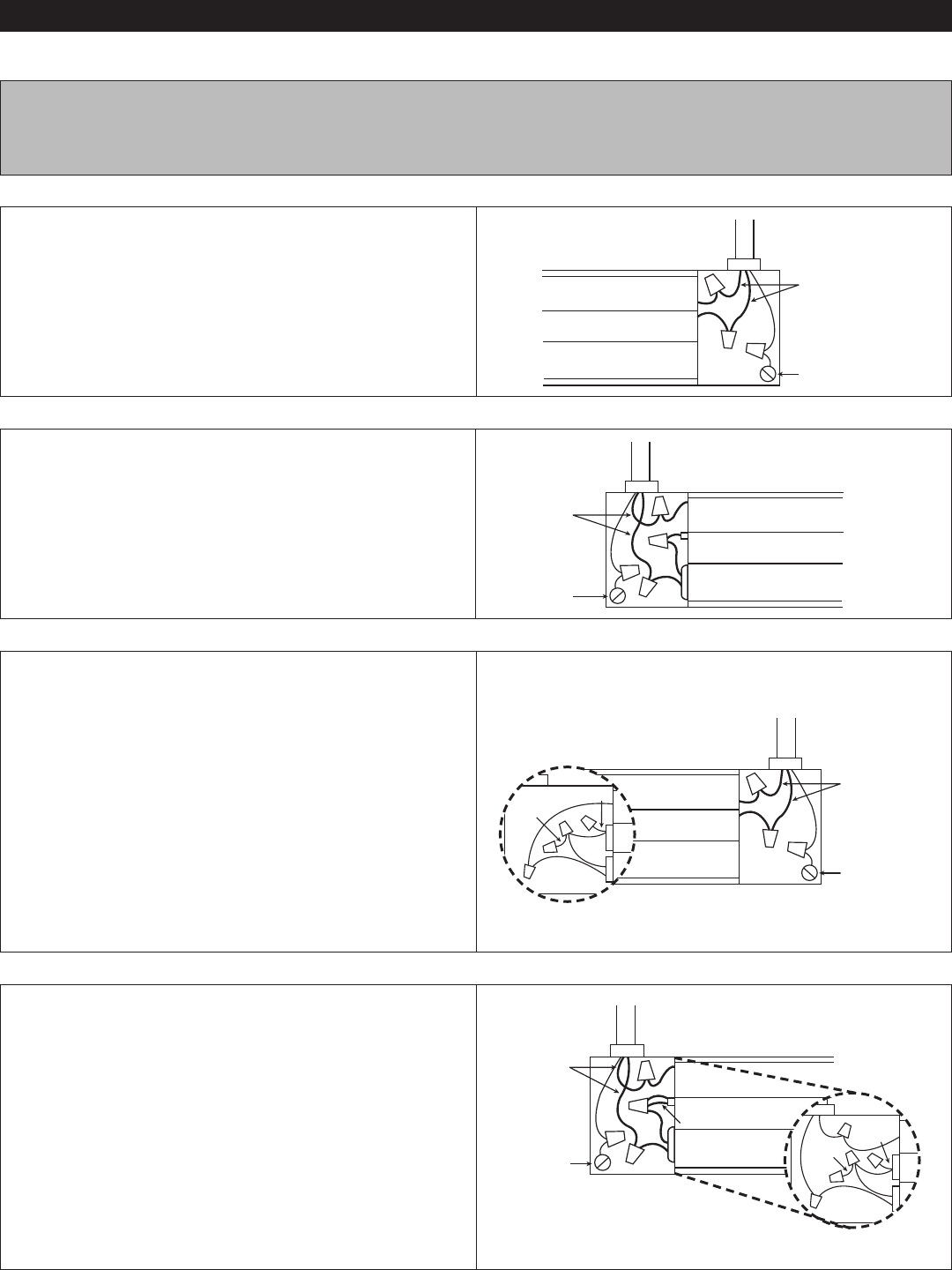
STANDARD BASEBOARD WIRING ON RIGHT SIDE
120V OR 240V SUPPLY (See Figure 8)
1. Connect one supply wire to one heater wire.
2
. Connect remaining supply wire to remaining heater wire.
3. Replace wiring compartment cover and secure with screw
previously removed.
4. Turn power back on at the electrical panel board.
STANDARD BASEBOARD WIRING ON LEFT SIDE
120V OR 240V SUPPLY (See Figure 9)
1. Connect one supply wire to one heater wire.
2. Connect remaining supply wire to remaining heater wire.
3. Replace wiring compartment cover and secure with screw
previously removed.
4. Turn power back on at the electrical panel board.
Installation Instructions
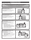
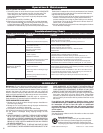
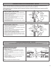
MULTI-WATT BASEBOARDS: WIRING ON RIGHT SIDE
MODEL 8F2025 (See Figure 10)
1. Connect one supply wire to one heater wire.
2. Connect remaining supply wire to remaining heater wire.
3. Replace wiring compartment cover and secure with screw
previously removed.
4. Selecting desired wattage
a. For 2500 watt applications: No action is required.
Heater is factory set for 2500 watts.
b. For 2000 watt applications: Remove left wiring compartment
cover. Cut red wire and cap both loose ends with
approved wire connectors, or wrap both loose ends with
electrical tape. Replace wiring compartment cover and
secure with screw previously removed.
5. Turn power back on at the electrical panel board.
Figure 10
Right Side
Wiring Shown
Model 8F2025 -
Factory set for
2500 watts
Refer to the wiring diagram below that corresponds to your heater application.
For single wattage baseboards, refer to “Standard Baseboards.”
For model 8F2025, refer to “Multi-Watt Baseboards.”
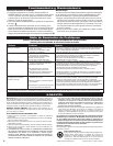
MULTI-WATT BASEBOARDS: WIRING ON LEFT SIDE
MODEL 8F2025 (See Figure 11)
1. Connect one supply wire to one heater wire.
2. Connect remaining supply wire to remaining heater wire.
3. Selecting desired wattage
a. For 2500 watt applications: No action is required.
Heater is factory set for 2500 watts.
b. For 2000 watt applications: Cut red wire and cap both loose
ends with approved wire connectors, or wrap both loose
ends with electrical tape.
4. Replace wiring compartment cover and secure with screw
previously removed.
5. Turn power back on at the electrical panel board.
Figure 11
Left Side
Wiring Shown
B
aseboard Heater
T
o Supply
Side ‘B’ Shown
Supply Wires
G
round
Baseboard Heater
To Supply
Side ‘B’ Shown
Supply Wires
Ground
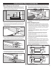
STEP 2: Baseboard Wiring (continued)
B
aseboard Heater
T
o Supply
Side ‘A’ Shown
Supply Wires
Ground
Baseboard Heater
To Supply
Side ‘A’ Shown
Supply Wires
Ground
2000 Watt Configuration
Left Side of Baseboard Shown
2000 Watt Configuration
Left Side of Baseboard Shown
4
Red
Wire
Red Wire
Red Wire
Red
Wire
Red
Wire