


NOTE: You do not need to disassemble any additional parts to mount
the heater.
Installation Instructions
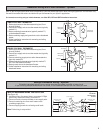
WIRING
C
OMPARTMENT COVER
MOUNT
SECURELY
TO WALL
Figure 7
Model
8F2025
Only
SUPPLY
WIRES
GROUND
WIRE
GROUNDING PIGTAIL
WIRE CONNECTOR
B
A
GROUND
DO NOT DISCONNECT
Figure 6
B
A
GROUND
DO NOT DISCONNECT
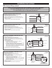
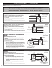
STEP 2: Baseboard Wiring
1. Verify the electrical supply wires are the same voltage as the
heater. Check heater specifications to ensure correct wiring.
Failure to do so may destroy the heater and void your warranty.
Both 120 volt and 240 volt baseboard wiring utilize 3 supply wires.
120 volt baseboard wiring: 1 hot, 1 neutral and 1 ground
240 volt baseboard wiring: 2 hot and 1 ground. No neutral needed.
For all baseboard wiring applications, both supply wires must be
connected to at least one (1) heater wire.
2. Connect the grounding lead to the grounding pigtail (copper wire)
with a connector (See Figure 4). It may be necessary to move ground
lead to the side you are wiring.
3. Disconnect one factory connector (See Figure 6. Model 8F2025 see
Figure 7). If wiring on the left side, disconnect factory connector
A. If wiring on the right side, disconnect factory connector B.
NOTE: There are no loose wires provided with the baseboard.
This is due to the ability to wire the baseboard on either the right
or left side of the heater.
4. Proceed to the next step.
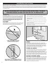
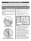
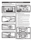
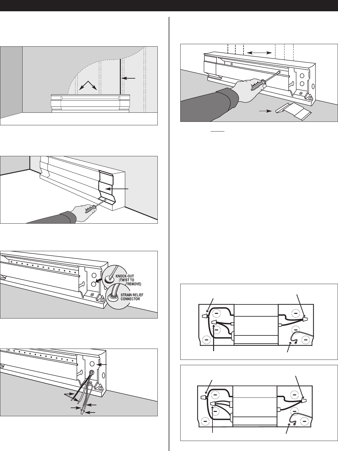
STEP 1: Mount Heater to Wall
1. Locate wall studs closest to supply wires and position heater
(
See Figure 1). NOTE: Wire connection is possible from either right
or left side of the baseboard heater.
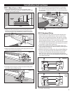
4. Pull supply wires through the connector and secure leaving 6 inch
wire leads for later use (See Figure 4).
5. Mount the heater securely to the wall with nails or screws going
i
nto at least two wall studs (See Figure 5). The back of the heater
has “star punch” dimples that allow nails or screws to easily pierce
the sheet metal.
S
TUDS
S
UPPLY
STUDS
F
LOOR
FINISHED
W
ALL
2. Remove the wiring compartment cover by removing the screw
(See Figure 2). The wiring compartment is an approved junction
box for the baseboard only. No additional junction box is required.
3. Remove the slotted knockout closest to the supply wires and install
a strain relief connector (See Figure 3).
JUNCTION BOX
W
IRING
COMPARTMENT
COVER
Figure 1
Figure 2
Figure 3
Figure 4
Figure 5
3