


5
Vertical Delivery Units, Model BV Series
Models BV-42 through BV-161 have 4 tapped holes
(1/2”-13) on the top surface for unit suspension.
Suspension can be made with threaded rods, pipes,
or ceiling hanger brackets. Models BV-193 through
BV-610 have angle-iron frame mounting brackets for
heavy-duty installation with applicable hardware.
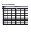
C. UNIT HEATER MOUNTING HEIGHT
Do not install unit above recommended maximum
mounting heights or below the minimum height of eight
feet. The height at which unit heaters are installed is
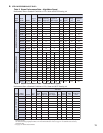
critical. Maximum mounting heights for all units are
listed in Table 1. Maximum mounting heights for Model
BV is given for units with or without air diffusion
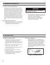
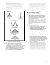
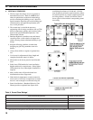
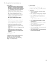
Figure 2: Vertical Air Delivery
No Defl ector
Two-Way Louver
4-Cone Anemostat
Truncone
accessories. Locate horizontal delivery unit heaters so
air streams of individual units wipe the exposed walls
of the building with either parallel or angular fl ow
without blowing directly against the walls. Heaters
should be spaced so the air stream from one supports
the air stream from another heater. Locate vertical
delivery unit heaters in the center area of the space to
be heated, using horizontal delivery unit heaters along
the walls where heat loss is usually greatest.
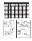
D. PIPING INSTALLATION
Horizontal and Vertical Unit Heaters
Note: Only make piping connections using two (2)
pipe wrenches. One wrench is used as a “back-up”
while the other wrench is used for applying force
necessary to tighten the fi tting.
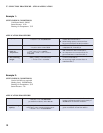
The illustrations, on page 6, suggest four (4) different
piping confi gurations. Refer to the ASHRAE Guide &
Specialty Manufacturer for selection of fi lter, piping
traps and other specialty sizing. Piping is typical for
unit heaters.
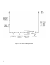
E. WIRING INSTRUCTIONS
1. Disconnect power supply before making wiring
connections to prevent electrical shock and
equipment damage. All units must be wired strictly
in accordance with wiring diagram (Figure 3).
2. All wiring must be done in accordance with the
National Electric Code and applicable local codes.
In Canada, wiring must conform to the Canadian
Electric Code. It is recommended that all wiring be
adequately grounded.
3. Electric wiring must be sized to carry the full load
amp draw of the motor, starter, and any controls that
are used with the unit heater. Overcurrent protectors
should be sized based on motor current rating shown
on the unit serial plate, and applicable national
electric code procedures.
4. All units should be installed with an electrical
junction box. Junction boxes are either integral to
the motor or to be attached to the unit casing. Units
with explosion-proof motors have an explosion-
proof junction box attached to the motor. Any
damage to or failure of Burnham Hydronics heater
units caused by incorrect wiring of the units is not
covered by Burnham Hydronics standard warranty.