


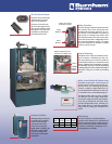

The flame can be continuously
modulated from an orange
glow to a full blue flame.
The burner is located on the
top of the heat engine forcing
the heat down while the water
flows upward. This allows the
condensation to drain down
and away from the boiler.
CHG Site Glass & Burner
Abundant domestic hot water
is available with a matching
Alliance indirect-fired hot
water heater. Select from
several sizes to meet your
specific needs. In addition, the
CHG boiler control module
is preset for domestic hot
water priority and set point
temperature.
Domestic Hot Water
CHG boilers utilize a pre-mix combustion assem-
bly that includes a modulating gas valve, vari-
able speed blower and a venturi to provide an
optimal fuel/air mixture to a stainless steel mesh
burner. Together these components accurately
and efficiently help control the fully modulating
combustion process which automatically adjusts
the boiler’s firing rate to match your heating
needs.
Premix Technology
Negative regulated gas valve
with factory set outlet pressure.
Venturi
Variable
Speed
Blower
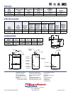
The CHG incorporates a sealed combustion
system that uses outside air for combustion and
the safe and proven AL29-4C stainless steel ma-
terial for venting the exhaust. Both horizontal
(“sidewall”) and vertical (“through-the-roof”)
venting options are available.
CHG Venting
Boiler
Model
Horizontal
Vent Max.
Vertical
Vent Max.
Vent
Diameter
CHG150 55 ft. 49.5 ft. 3 in.
CHG225 55 ft. 47 ft. 4 in.
The MCBA microprocessor control manages all
boiler functions including supervising the com-
bustion process and monitoring key operating
functions. Included is a digital display that can
provide detailed boiler information as well as be
an invaluable service and troubleshooting tool.
The MCBA module stores set points for boiler
and domestic hot water supply temperatures,
and monitors supply and return water tempera-
tures, flue gas temperature, the flame sensor,
and the included outdoor reset. The boiler con-
trol module allows for continuous modulation
(firing rates) by varying the combustion fan
speed.
Boiler Control Module & Outdoor Reset
Supply
Manifold
Return
Manifold
The CHG castings incorporate a multi-pass water
flow with the return water entering the lower
manifold and progressing upward to the sup-
ply manifold. This counterflow from bottom to
top provides for maximum heat transfer while
the serpentine pattern offers low pressure drop.
Each section’s water flow is independent with no
port connections between sections. The supply
and return manifolds are designed to balance
the flow across all sections.
Boiler Operations
Cutaway view showing
actual water flow path.