


2
The following terms are used throughout this manual to bring attention to the presence of hazards of various risk
levels.
WARNING
Indicates a potentially hazardous situation which,
if not avoided, could result in death, serious injury
or substantial property damage.
CAUTION
Indicates a potentially hazardous situation which,
if not avoided, may result in moderate or minor
injury or property damage.
Basic Operation
A. General. This water boiler is equipped with controls
for proper operation. All controls must be in proper
working order. Contact a qualied service agency to
provide annual maintenance as specied in Installation,
Operating and Service Instructions.
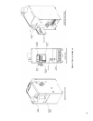
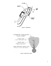
1. Limit. See Figure 1. A device which automatically
interrupts boiler operation when the water
temperature exceeds the set point. Maximum
allowable temperature is 220°F.
Original equipment with this boiler is U.S. Boiler
IQ Control and Limit Rated Sensor combination.
The IQ Control shuts off boiler main burners when
boiler water temperature exceeds pre-programmed
IQ control water temperature set point. Boiler main
burners will re-light automatically, providing the call
for heat is present, when boiler water temperature
falls below pre-programmed control water
temperature set point less the set point differential.
2. Flame Rollout Switch. See Figure 1. A device
which automatically interrupts boiler operation
when ames or excessive heat are present in the
combustion area enclosure. The control is a single
use device. The control is located in the combustion
area enclosure. If the control was activated to
interrupt boiler operation, do not attempt to place
boiler in operation. Contact a qualied service
agency.
WARNING
Service on this boiler should be undertaken only
by trained and skilled personnel from a qualied
service agency.
WARNING
Do not reset Blocked Vent Switch unless a
qualied service agency has determined and
corrected the cause of any blockage in the vent
system or chimney.
3. Blocked Vent Switch See Figure 1. A device
which automatically interrupts boiler operation
when excessive vent system blockage occurs. If the
control was activated to interrupt boiler operation,
do
not attempt to place boiler in operation. Contact
a qualied service agency.
4. Electronic Ignition System - see Figure 1. The
Electronic Ignition (EI) System consists of:
a. a solid state ignition control with integral
ignition module to initiate, monitor and stop
burner operation.
b. a combination gas valve to regulate gas ow to
the main burners.
c. a pilot burner to provide the ignition source for
the main burners.
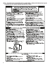
B. Instructions to place the boiler in operation and to turn
off the boiler are shown on the Operating Instruction
Label posted on the left jacket panel of the boiler. The
Operating Instruction Label is shown in Figure 2.
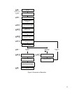
C. The Sequence of Operation is shown in Figure 3.
CAUTION
Should overheating occur or the gas supply fail to shut off, do not turn off or disconnect the electrical
supply to the pump. Instead, shut off the gas supply at a location external to the appliance.
En cas de surchauffe ou si I'admission de gaz ne peut étre coupée, ne pas couper ni débrancher
l'alimentation électrique de la pompe. Fermer plutôt le robinet d'admission de gaz à l'extérieur de I'appareil.
Do not use this boiler if any part has been under water. Immediately call a qualied service technician to
inspect the boiler and to replace any part of the control system and any gas control which has been under
water.