


ALTERNATIVES FOR WALL PROTECTION
Example: The rear clearance for the Model 80 from page 12 is 26". (Measurement A.) This clearance may be
reduced by 66% by using either of the wall protection devices mentioned below.
Tested and Listed Wall Protector
Clearances to combustibles may be reduced if a tested and listed wall protector is installed over a combustible
surface when the following condition exist:
1. A dead air space or 1" separates the listed and tested wall protector from the combustible surface.
2. The tested and listed wall protector extends from floor to ceiling with a 1" clearance for air circulation at both
the floor and ceiling.
3. The 1" spacers (preferable ceramic rather than metal) must be located at the corners rather than behind the
heater or the chimney connector.
Unlisted and Untested Wall Protector
Wall protectors may be constructed of masonry, 24 gauge or thicker sheet metal, or non-combustible 1/2" thick
insulation board. Conditions 2 and 3 above must be observed but the air space in condition 1 must be increased to 1
1/2".
FINAL CHECK
1. Recheck the specified clearances.
2. Remove all foreign material from the firebox area.
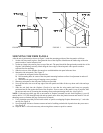
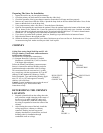
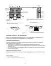
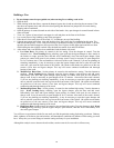
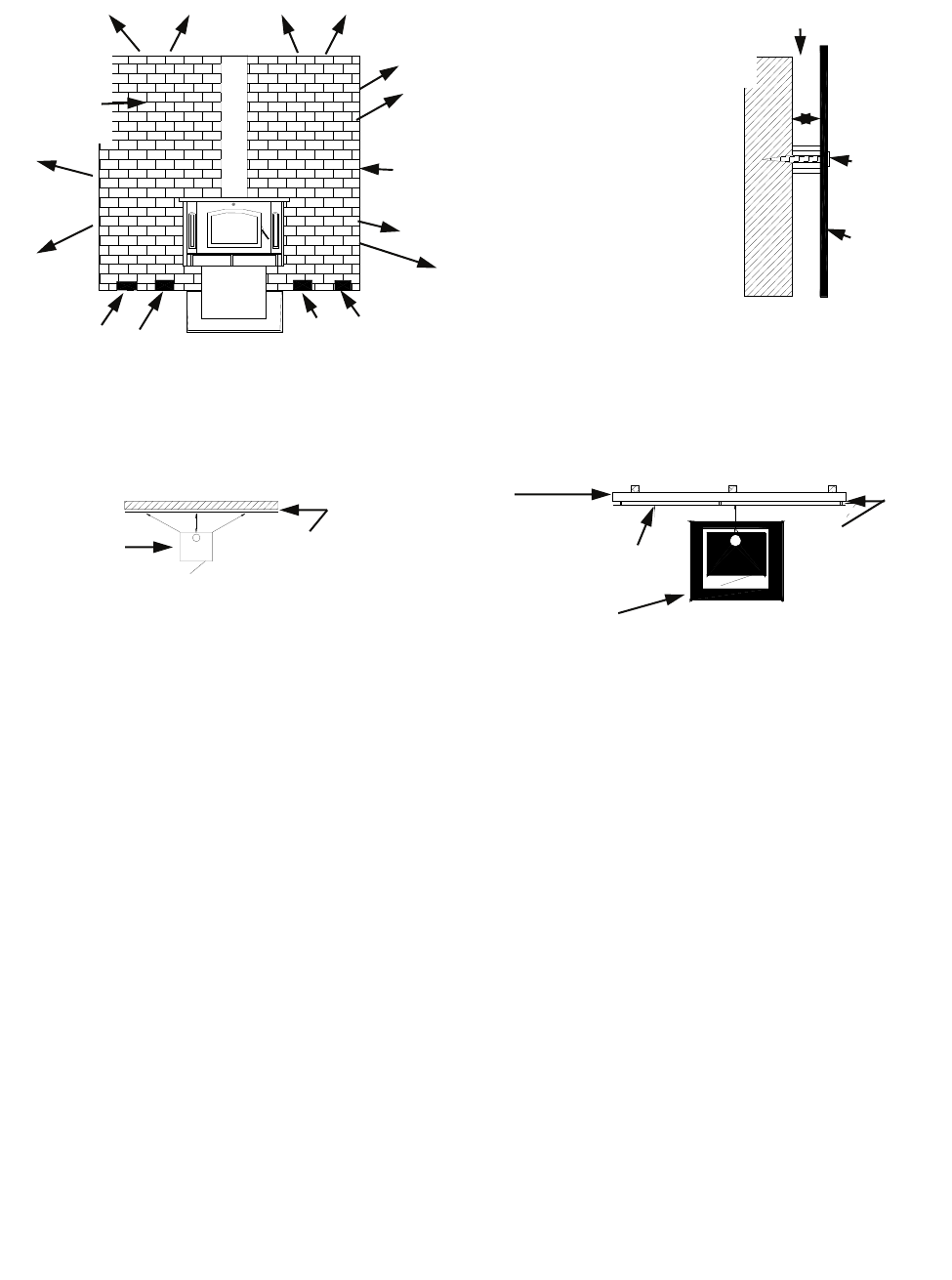
BRICK
CLEARANCE
REDUCTION
SYSTEM
BRICK WALL SPACED
OUT 1 INCH FROM
PROTECTED SURFACE
AIR CIRCULATION
LEAVE 1 INCH
CLEARANCE FOR AIR
CIRCULATION
FLOOR
AIRSPACE
COMBUSTIBLE
WALL
1”
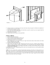
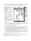
NAIL OR
SCREW
ANCHOR
MINIMUM
24 GAUGE
SHEET
METAL
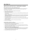
1 INCH NON-COMBUSTIBLE SPACER SUCH AS STACKED WASH-
ERS, SMALL DIAMETER PIPE, TUBING, OR ELECTRICAL CON-
DUIT.
DO NOT USE FASTENERS DIRECTLY BEHIND CHIM-
NEY CONNECTOR OR STOVE
COMBUSTIBLE
WALL
TOP VIEW
NON-COMBUSTIBLE
SPACERS
MINIMUM
24 GAUGE
SHEET METAL
FLOOR PROTECTOR
SHEET METAL CLEARANCE REDUCTION SYSTEM
FIGURE 12
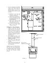
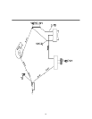
BRICK WALLS MAY BE ATTACHED TO COMBUSTIBLE WALLS
USING WALL TIES. IF BRICK IS USED, BE SURE FLOOR CAN
WITHSTAND THE WEIGHT OF THE BRICK.
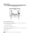
COMBUSTIBLE WALL
WOOD STOVE
CLEARANCE RE-
DUCTION SYSTEM
SPACED OUT 1
INCH.
16