


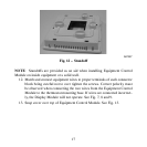
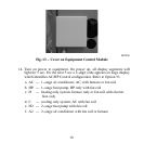
12
A07165
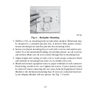
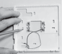
Fig. 6 − Backplate Mounting
3. Drill two 3/16−in. mounting holes in wall where marked. Thermostat may
be mounted to a standard junction box, if desired. Hole pattern on ther-
mostat mounting base matches junction box mounting holes.
4. Secure rear plastic mounting base to wall with 4 screws and anchors pro-
vided. To avoid unintended bending of wall plate plastic, use all 4 screws
and anchors Make sure all wires extend through hole in mounting base.
5. Adjust length and routing of each wire to reach proper connector block
and terminal on mounting base with 1/4−in. (6mm) extra wire.
6. Match and connect equipment wires to proper terminals of each connector
block being careful not to over tighten the screws. Correct polarity must
be observed when connecting the two wires from the Equipment Control
Module to the thermostat mounting base. If wires are connected incorrect-
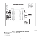
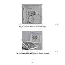
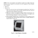
ly, the Display Module will not operate. See Fig. 7, 8 and 9.