


2
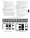
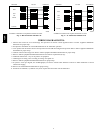
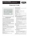
Table 1 – Model Selection and Wiring Diagram Chart
OUTDOOR UNIT
AIR CONDITIONER
1 Speed
HEAT PUMP
1 Speed
1---Stage Furnace Model AC See Fig. ---
2---Stage Furnace Model AC See Fig. Model HP See Fig. ---
Typical Fan Coil Model AC See Fig. Model HP See Fig. Model HP See Fig.
Var ia bl e --- Sp ee d Fan Coil (FK4D,
FV4, 40FK)
Model AC See Fig. Model HP See Fig. Model HP See Fig.
Install Thermostat
ELECTRICAL OPERATION HAZARD
Failure to follow this warning could result in personal injury
or death.
Before installing, modifying, or servicing system, main
electrical disconnect switch must be in the OFF position. There
may be more than 1 disconnect switch. Lock out and tag
switch with a suitable warning label.
!
WARNING
1. Turn OFF all power to unit.
2. If an existing thermostat is being replaced:
a. Remove existing thermostat from wall.
b. Disconnect wires from existing thermostat, 1 at a time.
Be careful not to allow wires to fall back into the wall.
c. As each wire is disconnected, record wire color and
terminal marking.
d. Discard or recycle old thermostat.
NOTE: Mercury is a hazardous waste and MUST be disposed of
properly.
3. Open thermostat (mounting base) to expose mounting
holes. The base can be removed to simplify mounting. Snap
apart carefully to separate mounting base from remainder of
thermostat.
NOTE: If thermostat will not separate, insert a small screwdriver
into top slots for ease of opening.
4. Route thermostat wires through large hole in mounting
base. Level mounting base against wall (for aesthetic value
only -- thermostat need not be leveled for proper operation)
and mark wall through 2 mounting holes.
5. Drill two 3/16” (5mm) mounting holes in w all where
marked.
6. Secure mounting base to wall with 2 anchors and screws
provided, (additional anchoring holes available for more se-
cure mounting if needed) making sure all wires extend
through hole in mounting base.
7. Adjust length and routing of each wire to reach proper ter-
minal and connector block on mounting base with 1/4”
(6mm) of extra wire. Strip only 1/4” (6mm) of insulation
from each wire to prevent adjacent wires from shorting
together when connected.
8. Match and connect equipment wires to proper terminals of
the connector blocks. (See Table 1.)
ELECTRICAL OPERATION HAZARD
Failure to follow this caution may result in equipment damage
or improper operation.
Improper wiring or installation may damage the thermostat
Check to make sure wiring is correct before proceeding with
installation or turning on unit.
CAUTION
!
9. Push any excess wire into wall and against mounting base.
Seal hole in wall to prevent air leaks. Leaks can affect
operation.
10. Snap case back together.
11. Close thermostat assembly making sure pins on back of
circuit board align with sockets in c onnector .
12. Turn ON power to unit.
NOTE: If a common wire has not been connected, two AA
batteries must be used to power the thermostat.
Make sure the customer is informed about changing the batteries
every 12 months, if a common wire is not available.
If a common wire is connected, then batteries are not needed for
any reason. Batteries may be installed if desired but the thermostat
will not draw power from them.
Set Thermostat Configuration
Configuration options are intended to be selected at installation and
are normally not modified by the home owner. These options are
not discussed in the Homeowner’s Guide and therefore must be
made as part of the installation. A special procedure allows entry
into the configuration mode. The thermostat will automatically exit
this mode if no button is pressed for 3 minutes. While in the
configuration mode, up to 14 option choices can be made:
Option 01: Anticipator setting
Option 02: Clean filter setting
Option 03: Fahrenheit or Celsius selection
Option 04: Enable fan (G) on with W output
Option 05: HP / AC
Option 07: Enable zoning
Option 10: O (reversing valve) ON with Heat or Cool (present on
Heat Pump models only)
Option 13: Room temperature offset adjustment
Option 15: Enable AUTO mode
Option 18: Backlight Configuration
Option 19: Equipment Present
Option 21: Keypad Lockout
An explanation for each of these and how to enter the
configuration mode follows.
T2SN