


4
pressing UP and FAN buttons simultaneously or changing the
setpoint will override the timer for 1 cycle.
Minimum on Timer
Once the equipment has turned on, it will remain on for a
minimum of 3 minutes regardless of demand. However, the
equipment can turn off in less than 3 minutes if a change in
setpoint, or a change in mode occurs.
Staging Timer
If the thermostat is a heat pump model, it has 2--stage heat
capability. In normal operation there is a 15--minute delay between
the first and second stages of heat. The Y output will energize first,
then 15 minutes later, W is allowed to come on if the thermostat
determines it is not satisfying the demand.
However, if the heating demand is greater than 5_F/3_C, there will
be only a 30 second delay before bringing on W.
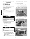
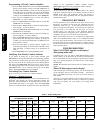
Auxiliary Heat Indicator
When operating a heat pump and either auxiliary heat or
emergency heat is active, a front mounted LCD indicates this
condition.
A07821
Error Messages
If the room temperature sensor fails, two dashes (----) will appear in
the temperature display and all heating and cooling outputs will be
turned off. The thermostat must be replaced.
If the internal non--volatile memory fails, E4 will alternately flash
with the temperature on the display and all heating and cooling
outputs will be turned off. The thermostat must be replaced.
Step 5 — Check Thermostat Operation
Fan Operation
1. Press FAN button. This will start continuous fan operation.
FAN ON icon will turn on.
2. Press FAN button again. This will stop continuous fan oper-
ation. FAN ON icon will turn off.
Heating Operation
1. Press H/C button until HEAT is displayed.
2. Press UP button until LCD readout reads 3_F/2_C above
room temperature. Press UP and FAN buttons simultan-
eously to defeat timers. Heating system should begin to op-
erate immediately.
3. For HP thermostats only, press H/C button until EMHT
(emergency heat) appears. Press UP and FAN buttons sim-
ultaneously to defeat timers. Emergency heating (W is ON,
Y is OFF) should begin immediately.
Cooling Operation
1. Press H/C button until COOL is displayed.
2. Press DOWN button until LCD readout reads 3_/2_Cbe-
low room temperature. Press UP and FAN buttons simultan-
eously to defeat timers. Cooling system should begin to op-
erate immediately.
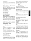
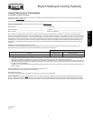
Table 1 shows the thermostat outputs for each available stage of
heating or cooling. It may be useful in checkout or
troubleshooting.
Table 1 – Outputs
EQUIPMENT
CONFIGURATION
OPTION #1
THERMOSTAT
FACTORY
CONFIGURATION
COOL
STAGE 1
HEAT
STAGE 1
HEAT
STAGE 2
EM HEAT
AC, PC AC, HP Y, G W --- --- --- ---
HP, PH
RVS = C
HP Y, G, O /B Y, G Y, G, W W
HP, PH
RVS = H
HP Y,G Y, G, O /B Y, G, W, O /B W
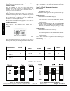
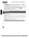
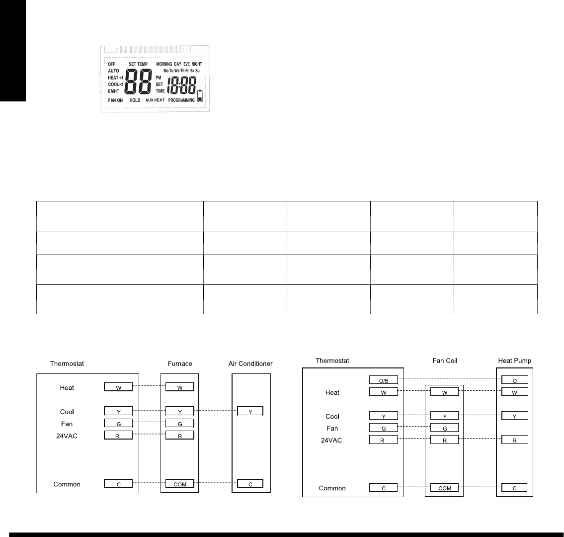
WIRING DIAGRAMS
A06566
Fig. 1 -- A/C Thermostat Typical Installation
A06567
Fig. 2 -- HP Thermostat Typical Installation
Manufacturer reserves the right to discontinue, or change at anytime, specificati ons or designs without notice andwithout incurring obligations.
E2010B ryant Heating &Cooling Systems 7310W. MorrisSt. Indianapolis, IN 46231 Printed inU.S.A. EditionDate: 02/10
Replaces: IIT1--- PAC--- 07
Catalog No. IIT1---P
A
C --- 08
T1--PAC / T1--PHP