


MAINTENANCE AND SERVICE
This section discusses maintenance that should be performed by
your dealer and care you, as the owner, may wish to handle for
your new system.
A. Routine Maintenance
All routine maintenance should be handled by skilled, experienced
personnel. Your dealer can help you establish a standard proce-
dure.
For your safety, keep the unit area clear and free of combustible
materials, gasoline, and other flammable liquids and vapors.
To assure proper functioning of the unit, flow of condenser air
must not be obstructed from reaching the unit. Clearance from the
top of the unit is 48 in. Clearance of at least 36 in. is required on
sides except the power entry side (42 in. clearance) and the duct
side (12 in. minimum clearance).
B. Maintenance and Care for the Equipment Owner
Before proceeding with those things you might want to maintain
yourself, please carefully consider the following:
WARNING: 1. TURN OFF ELECTRICAL POWER
TO YOUR UNIT BEFORE SERVIC-
ING OR PERFORMING MAINTE-
NANCE. ELECTRIC SHOCK COULD
CAUSE SERIOUS INJURY OR
DEATH.
2. When removing access panels or performing mainte-
nance functions inside your unit, be aware of sharp
sheet metal parts and screws. Although special care is
taken to keep sharp edges to a minimum, be extremely
careful when handling parts or reaching into the unit.
AIR FILTERS
The air filter(s) should be checked at least every 3 or 4 weeks and
changed or cleaned whenever it becomes dirty. Dirty filters
produce excessive stress on the blower motor and can cause the
motor to overheat and shut down.
This unit must have air filters in place before it can be operated.
These filters can be located in one of at least two places. In many
applications the installer will provide return air filter grilles
mounted on the wall or ceiling of the conditioned structure. In the
instance of filter grilles, the filters can simply be removed from the
grille and replaced.
The other typical application is an accessory filter rack installed
inside the unit itself. The following information is given to assist
in changing filters used in these internal filter racks.
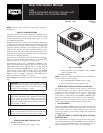
Table 1 indicates the correct filter size for your unit. Refer to Fig.
2 to access filters installed in the accessory filter rack.
To replace or inspect filters in accessory filter rack (See Fig. 2):
1. Remove the filter access panel using a 5/16-in. nut driver.
2. Remove the filter(s) by pulling it out of the unit. If the
filter(s) is dirty, clean or replace with a new one.
When installing the new filter(s), note the direction of the airflow
arrows on the filter frame.
If you have difficulty locating your air filter(s) or have questions
concerning proper filter maintenance, contact your dealer for
instructions. When replacing filters, always use the same size and
type of filter that was supplied, originally, by the installer.
CAUTION: Never operate your unit without the filter(s)
in place. Failure to heed this warning may result in
damage to the blower motor and/or compressor. An
accumulation of dust and lint on internal parts of your
unit can cause loss of efficiency and , in some cases, a
fire.
FANS AND FAN MOTOR
Periodically, check the condition of fan wheels and housings and
fan-motor shaft bearings. Contact your dealer for the required
annual maintenance.
INDOOR AND OUTDOOR COILS
Cleaning of the coils should only be done by qualified service
personnel. Contact your dealer for the required annual mainte-
nance.
CONDENSATE DRAIN
The drain pan and condensate drain line should be checked and
cleaned at the same time the cooling coils are checked by your
dealer.
COMPRESSOR
All compressors are factory-shipped with a normal charge of the
correct type refrigeration grade oil. A compressor should rarely
require additional oil.
CONDENSER FAN
CAUTION: Do not poke sticks, screwdrivers, or any
other objects into revolving fan blades. Injury or equip-
ment damage may result.
The fan must be kept free of all obstructions to ensure proper
cooling. Contact your dealer for any required service.
ELECTRICAL CONTROLS AND WIRING
Electrical controls are difficult to check without proper instrumen-
tations. If there are any discrepancies in the operating cycle,
contact your dealer and request service.
TABLE 1—INDOOR-AIR FILTER DATA
UNIT SIZE FILTER SIZE
704B024-030 20x20x1
704B036 20x24x1
704B042-060 24x30x1
Fig. 2—Accessory Filter Rack Access Panel
C99094
ACCESS PANEL
FILTER ACCESS
PANEL*
*For accessory filter rack.
—2—