


3
sorbed from the outsideair. So,to maintain energy--efficient opera-
tion, your unit has an automatic defrost mode.
The defrost mode starts at a preset time interval of 60 minutes, al-
though, it may be reset to 30, 90 or 120 minutes. Defrost will start
atthe preset timeonly if the ice is sufficient to interfere with normal
heating operation.
After the ice is melted from the coil, or after a maximum of 10 min-
utesin defrostmode,theunitautomatically switchesbackto normal
heating operation.
Do notbe alarmed ifsteam orfog appearsattheoutdoor unitduring
defrost mode. Water vapor from the melting ice may condenseinto
a mist in the cold outside air.
During certain weather conditionssuch as heavy snow andfreezing
rain it is not uncommon for ice to build up on the unit grille. This is
normal for these weather conditions. Do not attempt to remove the
ice from the unit grille. This condition will not affect the proper
function of the unit and will clear within a few days.
Emergency Heating Mode
In the event of primary unit heat failure, the emergency heat mode
allows your supplemental heating source to keep your home or of-
ficewarmuntil yourunitcanbe serviced. Contactyourdealerin the
event of primary unit heat failure.
MAINTENANCE AND SERVICE
This section discusses maintenance that should be performed by
your dealer and careyou, as theowner, may wish to handle foryour
new unit.
Routine Maintenance
All routine maintenance should be handled by skilled, experienced
personnel. Your dealer can help you establish astandard procedure.
To assure proper functioning of theunit,flow ofcondenser air must
not be obstructed from reaching the unit.Clearance from the top of
the unit is 48 in. (1219 mm). Clearance of at least 36 in. (914 mm)
is required on sides except the power entry side (42 in. [1067 mm]
clearance) and the duct side (12 in. [305 mm] minimum clearance).
Maintenance and Care for the Equipment Owner
Before proceeding with those things you might want to maintain
yourself, please carefully consider the following:
FIRE, EXPLOSION, ELECTRICAL SHOCK, CUT
HAZARD
Failure to follow this warning could result in personal injury,
death or property damage.
1. TURN OFF ELECTRICAL POWER TO YOUR UNIT
BEFORE SERVICING OR PERFORMING
MAINTENANCEAND INSTALL A LOCK--OUTTAG.
2. When removing accesspanels or performing maintenance
functions inside your unit, be aware of sharp sheet metal
parts and screws. Although special care is taken to reduce
sharp edges to a minimum, be extremely careful when
handling parts or reaching into the unit.
!
WARNING
Air Filters
The air filter(s) should be checked every 3 or 4 weeks and changed
or cleaned whenever it becomes dirty. Dirty filters produce exces-
sive stresson the blower motor and can cause the motor to overheat
and shut down.
This unit must have an air filter in place before it can be operated.
Thesefiltersshould be locatedin atleast oneof twoplaces. In many
applications, the installer will provide return air filter grilles
mounted on the wall or ceiling of the conditioned structure. In the
instance of filter grilles, the filters can simply be removed from the
grille and replaced.
The other typical application is an accessory filter rack installed in-
side the unit itself. The following information is given to assist in
changing filters used in these internal filter racks.
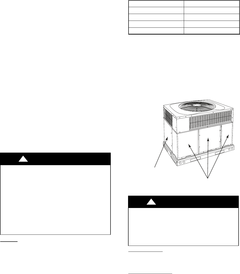
Table 1 indicates the correct indoor filter size for your unit. Refer
to Fig.3 to access filters installed in the accessory filter rack. Ifusing
an Accessory Filter Rack, refer to the Installation Instructions pro-
vided with it for correct filter sizes and quantities.
Table 1—Air Filters Located Inside Unit
(For Replacement Purposes)
Unit Size Filter Size in. (mm)
A24 20x20x1 (508x508x25)
A30 20x24x1 (508x610x25)
A36---A42 24x30x1 (610x762x25)
A48---A60 24x36x1 (610x914x25)
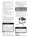
To replace or inspect filters in accessory filter rack:
1. Remove the filter access panel (See Fig. 3) using a 5/16--in.
nut driver.
2. Removethe filter(s)bypullingit out ofthe unit. Ifthefilter(s)
is dirty, clean or replace with a new one.
Wheninstalling the new filter(s), note the direction oftheairflow ar-
rows on the filter frame.
If you have difficulty locating your air filter(s) or have questions
concerning proper filter maintenance, contact your dealer for in-
structions. When replacing filters,alwaysusethesame size andtype
of filter that was supplied originally by the installer.
Access Panels
Filter Access Panel
For Accessory Filter Rack
A09044
Fig. 3 -- Accessory Filter Rack Access Panel
FIRE AND UNIT OPERATION HAZARD
Failure to follow this warning could result in personal injury,
death or property damage.
Never operate your unit without filters in place. An
accumulation of dust and linton internal parts of your unitcan
cause loss of efficiency.
!
WARNING
Fans and Fan Motor
Periodically check the condition of fan wheels and housings and
fan--motorshaftbearings.Contactyourdealerfortherequiredannu-
al maintenance.
Indoor and Outdoor
Coils
Cleaning of the coils should only be done by qualified service per-
sonnel. Contact your dealer for the required annual maintenance.