


2. Ice or frost tends to form on the coil during winter heating
operation. Your heat pump is designed to automatically
melt the ice. When in this defrost cycle, it is normal for
steam or fog to rise from the outdoor unit, and for water
to drain from the outside of unit. Do not be alarmed!
I. COOLING MODE
With the SYSTEM or MODE control set to COOL, your heat
pump will run in cooling mode until the indoor temperature is
lowered to the level you have selected. On extremely hot days,
your heat pump will run for longer periods at a time and have
shorter “off” periods than on moderate days.
II. HEATING MODE
With the SYSTEM or MODE control of your indoor thermostat set
to HEAT, your heat pump will run in heating mode until room
temperature is raised to the level you have selected. Of course,
your heat pump will run for longer periods to maintain a
comfortable environment on cooler days and nights than on
moderate ones.
III. SUPPLEMENTAL HEAT
Your heat pump is your primary heating source. Your system may
also be equipped with a supplemental heating source such as
electric heat. On cold days and nights, your system will automati-
cally turn on the supplemental heat in order to maintain the level
of comfort you have selected.
When your heat pump needs additional heat to keep you comfort-
able, your Bryant electronic thermostat will turn on the supple-
mental heat (if equipped) and display the “AUX HT” message.
IV. DEFROST MODE
When your heat pump is providing heat to your home or office and
the outdoor temperature drops below 45°F, moisture may begin to
freeze on the surface of the coil. If allowed to build up, this ice
would impede airflow across the coil and reduce the amount of
heat absorbed from the outside air. So, to maintain energy-efficient
operation, your heat pump has an automatic defrost mode.
The defrost mode starts at a preset time interval of 30 minutes,
although, it may be reset to 60, 90 or 120 minutes. Defrost will
start at the preset time only if the ice is sufficient to interfere with
normal heating operation.
After the ice is melted from the coil, or after a maximum of 10
minutes in defrost mode, the unit automatically switches back to
normal heating operation.
Do not be alarmed if steam or fog appears at the outdoor unit
during defrost mode. Water vapor from the melting ice may
condense into a mist in the cold outside air.
During certain weather conditions such as heavy snow and
freezing rain it is not uncommon for ice to build up on the unit
grille. This is normal for these weather conditions. Do not attempt
to remove the ice from the unit grille. This condition will not affect
the proper function of the unit and will clear within a few days.
V. EMERGENCY HEAT MODE
This allows your supplemental heating source to keep your home
or office warm until your heat pump can be serviced.
MAINTENANCE AND SERVICE
This section discusses maintenance that should be performed by
your dealer and care you, as the owner, may wish to handle for
your new heat pump.
A. Routine Maintenance
All routine maintenance should be handled by skilled, experienced
personnel. Your dealer can help you establish a standard proce-
dure.
For your safety, keep the unit area clear and free of combustible
materials, gasoline, and other flammable liquids and vapors.
To assure proper functioning of the unit, flow of condenser air
must not be obstructed from reaching the unit. Clearance from the
top of the unit is 48 in. Clearance of at least 36 in. is required on
sides except the power entry side (42 in. clearance) and the duct
side (12 in. minimum clearance).
B. Maintenance and Care for the Equipment Owner
Before proceeding with those things you might want to maintain
yourself, please carefully consider the following:
WARNING: 1. TURN OFF ELECTRICAL POWER
TO YOUR UNIT BEFORE SERVIC-
ING OR PERFORMING MAINTE-
NANCE. ELECTRIC SHOCK COULD
CAUSE SERIOUS INJURY OR
DEATH.
2. When removing access panels or performing mainte-
nance functions inside your unit, be aware of sharp
sheet metal parts and screws. Although special care is
taken to keep sharp edges to a minimum, be extremely
careful when handling parts or reaching into the unit.
AIR FILTERS
The air filter(s) should be checked at least every 3 or 4 weeks and
changed or cleaned whenever it becomes dirty. Dirty filters
produce excessive stress on the blower motor and can cause the
motor to overheat and shut down.
This unit must have air filters in place before it can be operated.
These filters can be located in one of at least two places. In many
applications the installer will provide return air filter grilles
mounted on the wall or ceiling of the conditioned structure. In the
instance of filter grilles, the filters can simply be removed from the
grille and replaced.
The other typical application is an accessory filter rack installed
inside the unit itself. The following information is given to assist
in changing filters used in these internal filter racks.
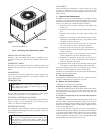
Table 1 indicates the correct filter size for your unit. Refer to Fig.
2 to access filters installed in the accessory filter rack.
Toreplaceorinspectfiltersinaccessoryfilterrack (See Fig. 2):
1. Remove the filter access panel using a 5/16-in. nut driver.
2. Remove the filter(s) by pulling it out of the unit. If the
filter(s) is dirty, clean or replace with a new one.
When installing the new filter(s), note the direction of the airflow
arrows on the filter frame.
If you have difficulty locating your air filter(s) or have questions
concerning proper filter maintenance, contact your dealer for
instructions. When replacing filters, always use the same size and
type of filter that was supplied, originally, by the installer.
CAUTION: Never operate your unit without the filter(s)
in place. Failure to heed this warning may result in
damage to the blower motor and/or compressor. An
accumulation of dust and lint on internal parts of your
unit can cause loss of efficiency and , in some cases, a
fire.
FANS AND FAN MOTOR
Periodically, check the condition of fan wheels and housings and
fan-motor shaft bearings. Contact your dealer for the required
annual maintenance.
TABLE 1—INDOOR-AIR FILTER DATA
UNIT SIZE FILTER SIZE
604B024-030 20x20x1
604B036 20x24x1
604B042-060 24x30x1
—2—