


When your heat pump needs additional heat to keep you comfort-
able, your Bryant electronic thermostat will turn on the supple-
mental heat (if equipped) and will display the “AUX HT” message.
IV. DEFROST MODE
When your heat pump is providing heat to your home and the
outdoor temperature drops below 45˚F, moisture may begin to
freeze on the surface of the coil. If allowed to build up, this ice
would impede airflow across the coil and reduce the amount of
heat absorbed from the outside air. So, to maintain energy-efficient
operation, your heat pump has an automatic defrost mode. The
defrost mode starts at a preset time interval of 90 minutes,
although, it may be reset to either 30 or 50 minutes. Defrost will
start at the preset time only if the ice is sufficient to interfere with
normal heating operation. After the ice is melted from the coil, or
after a maximum of 10 minutes in defrost mode, the unit
automatically switches back to normal heating operation.
Do not be alarmed if steam or fog appears at the outdoor unit
during defrost mode. Water vapor from the melting ice may
condense into a mist in the cold outside air. During certain weather
conditions such as heavy snow and freezing rain it is not
uncommon for ice to build up on the unit grille. This is normal for
these weather conditions. Do not attempt to remove the ice from
the unit grille. This condition will not affect the proper function of
the unit and will clear a few days.
PERFORMING ROUTINE MAINTENANCE
With the proper maintenance and care, your heat pump will
operate economically and dependably. Maintenance can be accom-
plished easily by referring to the following directions. However,
before performing maintenance, consider these important safety
precautions:
WARNING: Disconnect all electrical power to the in-
door air handler or furnace before removing access panels
to perform any maintenance. Disconnect power to both
the indoor and outdoor units. Note: There may be more
than 1 electrical disconnect switch. Electrical shock can
cause serious injury or death.
CAUTION: Although special care has been taken to
minimize sharp edges in the construction of your unit, to
avoid injury be extremely careful when handling parts or
reaching into the unit.
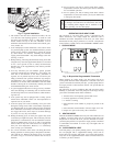
I. CHECK THE AIR FILTER
A dirty air filter will cause excessive strain on the compressor and
blower motor. This can cause the components to overheat and
automatically shut down. In the worst case, the components will
fail and need to be replaced. To avoid inefficient or failed
operation of your unit, CHECK THE FILTER(S) EVERY 3 TO 4
WEEKS. Replace filter(s) when necessary, or clean the filter(s) if
you have the reusable type.
Disposable filters should be replaced by similar, new filters of the
same dimensions.
Reusable, permanent filters should be washed in a solution of cold
water and mild detergent, then rinsed and thoroughly dried. THE
FILTER MUST BE COMPLETELY DRY BEFORE BEING
REINSTALLED. To avoid prolonged shutdown of your unit while
a filter is drying, you should have an extra filter on hand. This
allows you to rotate between the two with minimal downtime for
your comfort system. Extra filters may be purchased from your
dealer.
The filters(s) and filter rack for a packaged system are supplied
and installed by the contractor or dealer. Typically, the filter(s) and
rack are located in the return-air duct at the outdoor unit or behind
the return-air grille(s). Have your dealer show you the location of
your filter(s) and the procedures for removal and replacement.
If your system includes a high efficiency or electronic air cleaner,
refer to air cleaner User’s Manual for proper filter cleaning or
replacement.
II. OUTDOOR COIL
If grass clippings, leaves, shrubbery, and debris are kept away
from the unit, minimal care should be sufficient to keep the system
functioning properly. However, if the outdoor coil becomes dirty,
use a vacuum cleaner or shop vac with soft brush attachment to
clean the exterior surface. Vacuum coil surface using an up and
down motion. Be careful not to bend or damage fins.
If dirt is deep in the coil, contact your dealer for service. Do not
attempt this yourself.
III. OUTDOOR COIL—SEA COAST
If your unit is located near the ocean, special maintenance is
required. Ocean mist/breeze carries salt, which is corrosive to most
metals. Although your new unit is made out of galvanized metal
and is protected by top-grade paint, you should take the precaution
of additional maintenance which consists of periodically washing
the unit. By washing all exposed surfaces and coil, you will be
adding additional life to your unit. Please consult your installing
contractor for proper intervals/procedures for your geographic area
or service contact.
IV. UNIT SUPPORT
Your packaged heat pump unit should be maintained at a level
position. If its support should shift or settle so that the unit is no
longer level, you should correct the condition. Relevel it promptly
to assure water drains out of the unit. If you notice that water or ice
collects beneath the unit, arrange for it to be drained away from the
unit.
BEFORE YOUR REQUEST A "SERVICE CALL"
CHECK FOR THESE EASILY SOLVED PROBLEMS:
1. Check the indoor and outdoor disconnect switches. Verify
that circuit breakers are ON or that fuses have not blown.
2. Check for sufficient airflow. Check the air filter(s) for any
accumulations of dirt. Check for blocked return-air or
supply-air registers. Be sure registers are open and unob-
structed.
3. Check the settings on your indoor thermostat. If you desire
cooling, make sure that the temperature control selector is
set below room temperature and the SYSTEM or MODE
control is set to COOL or AUTO. If you require warmth,
make sure that the temperature control selector is set above
room temperature and the SYSTEM or MODE control is set
to HEAT or AUTO. The FAN control should be set to ON
for continuous blower operation or AUTO if you wish
blower to function only while your heat pump is operating.
If your comfort system still fails to operate, turn your
system off and contact your servicing dealer for trouble-
shooting and repairs. Specify your apparent problem, and
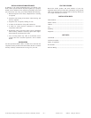
state the model and serial number of your equipment. (You
should have them recorded on the last page of this booklet.)
With this information, your dealer may be able to offer
helpful suggestions over the phone or save valuable time
through knowledgeable preparation for the service call.
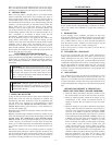
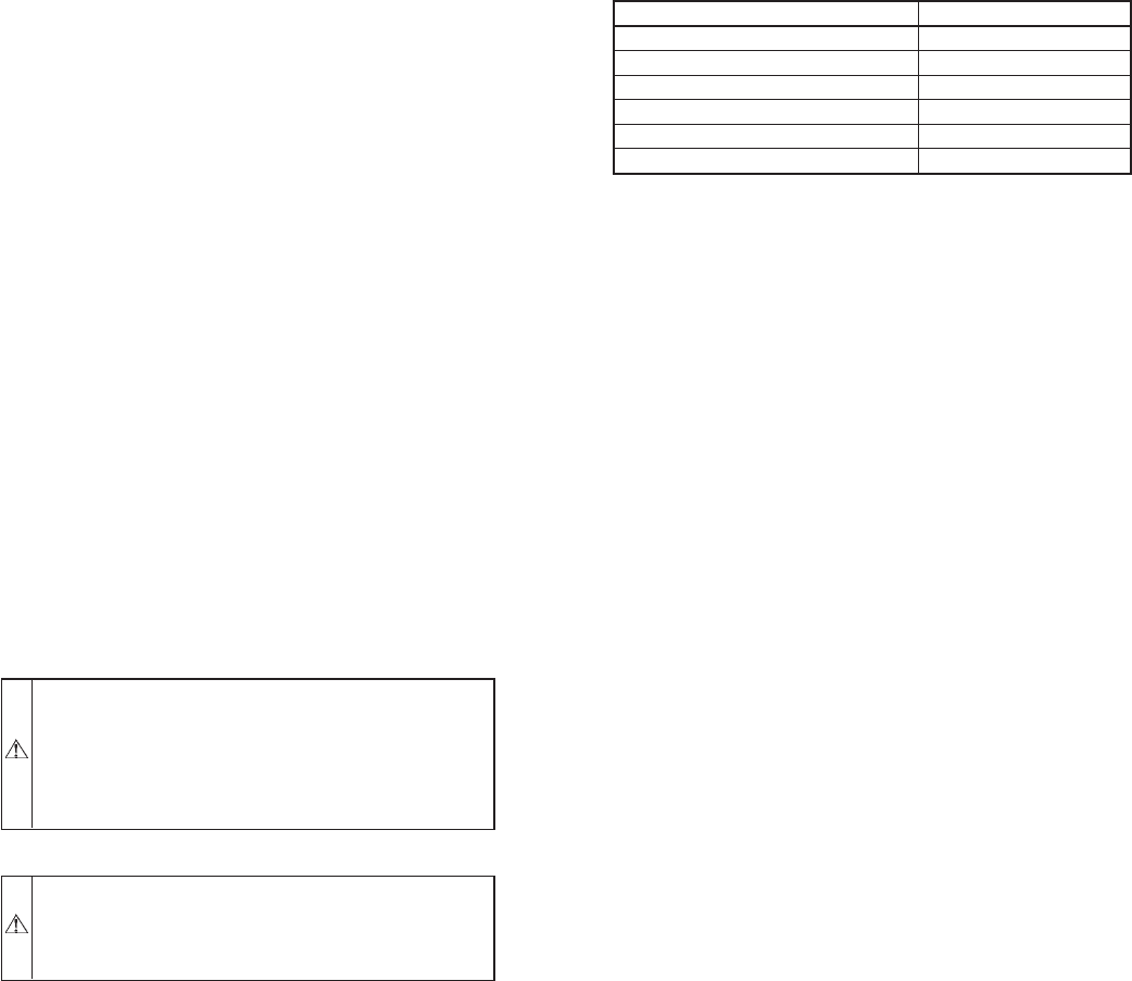
FILTER SIZE DATA
UNIT SIZE FILTER SIZE
601A018-30 20x20
601A036 20x24
601A042-060 24x30
602A024-030 20x20
602A036 20x24
602A042-060 24x30
—3—