—4—
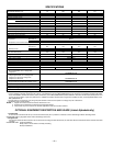
SPECIFICATIONS
* Permissible limits of the voltage range at which the unit will operate satisfactorily. Operation outside these limits may result in unit failure.
† If wire is applied at ambient greater than 30°C (86°F), consult Table 310-16 of the NEC (ANSI/NFPA 70). The ampacity of nonmetallic-sheathed cable (NM),
trade name ROMEX, shall be that of 60°C (140°F) conductors, per the NEC (ANSI/NFPA 70) Article 336-26. If other than uncoated (non-plated), 60 or 75°C
(140 or 167°F) insulation, copper wire (solid wire for 10 AWG and smaller, stranded wire for larger than 10 AWG) is used, consult applicable tables of the
NEC (ANSI/NFPA 70).
‡ Length shown is as measured 1 way along wire path between unit and service panel for a voltage drop not to exceed 2%.
** Time-delay fuse or circuit breaker.
NOTES:
1. Copper wire must be used from service disconnect to unit.
2. All motors and compressors contain internal overload protection.
3. This product may not be used in low-ambient applications below 55°F outdoor ambient.
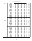
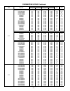
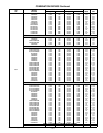
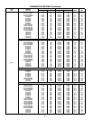
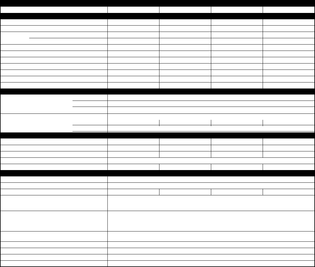
UNIT SIZE-SERIES
024-A 036-A 048-A 060-A, B
OPERATING WEIGHT (Lb)
171 228 266 311
ELECTRICAL
Unit Volts—Hertz—Phase
208/230-60-1 208/230-60-1 208/230-60-1 208/230-60-1
Operating Voltage Range*
187-253 187-253 187-253 187-253
Compressor— Rated Load Amps
10.6 14.1 19.9 26.3
Locked Rotor Amps
64.0 66.0 96.0 130.0
Condenser Fan Motor—Full Load Amps
0.5 0.8 1.1 1.1
Min Unit Ampacity for Wire Sizing
13.8 18.4 26.0 34.0
Min Wire Size (60°C Copper) AWG†
14 14 10 8
Min Wire Size (75°C Copper) AWG†
14 14 10 10
Max Wire Length (60°C) (Ft)‡
57 43 77 91
Max Wire Length (75°C) (Ft)‡
55 41 73 56
Max Branch Circuit Fuse Size**
20 30 40 50
COMPRESSOR AND REFRIGERANT
Compressor— Manufacturer
Bristol
Type
Reciprocating
Temperature and Current Protection
Internal Overload
Refrigerant— Type
Puron® (R-410A)
Amount (Lb)
6.0 8.9 11.5 13.1
Metering Device
Puron Balance Port Hard Shutoff TXV
CONDENSER COIL AND FAN
Coil—Face Area (Sq Ft)
10.8 18.2 18.2 18.2
Fins per In.—Rows—Circuits
25-1-2 25-1-3 20-2-5 20-2-5
Fan Motor—HP and RPM (PSC Type)
1/15 and 825 1/8 and 825 1/5 and 825 1/5 and 825
Volts—Hertz—Phase
208/230-60-1
Condenser Airflow (CFM)
1500 2500 3000 3100
OPTIONAL EQUIPMENT
Support Feet
KSASF0101AAA
Coastal Filter
KAACF0801MED
Bi-Flow Balance Port TXV (Hard Shut-off)
KSATX0201PUR KSATX0301PUR KSATX0401PUR KSATX0501PUR
Thermostat, Auto Changeover,
Non-Programmable, °F/°C, 1-stage heat/
1-stage cool
TSTATBBNAC01-B
Thermostat, Auto Changeover,
7-Day Programmable, °F/°C, 2-stage heat/
2-stage cool in AC mode, 3-stage heat/
2-stage cool in HP mode
TSTATBBP2S01-B
Thermidistat Control, Programmable/Non-
Programmable Thermostat with Humidity Control
TSTATBBPRH01-B
Outdoor Air Temperature Sensor
TSTATXXSEN01-B
Backplate for Non-Programmable Thermostat
TSTATXXNBP01
Backplate for Programmable Thermostat
TSTATXXPBP01
Thermostat Conversion Kit (4 to 5 wire)—10 Pack
TSTATXXCNV10
OPTIONAL EQUIPMENT DESCRIPTION AND USAGE (Listed Alphabetically)
1.
Coastal Filter
A mesh screen inserted under the top cover and inside the base pan to protect the condenser coil from salt damage without restricting airflow.
SUGGESTED USE:In geographic areas where salt damage could occur.
2.
Support Feet
Four stick-on plastic feet which raise the unit 4 in. above the mounting pad. This allows sand, dirt, and other debris to be flushed from the unit base; minimizes
corrosion.
SUGGESTED USE: Coastal installations.
Windy areas or where debris is normally circulating.
Rooftop installations.


