


CAUTION: To prevent improper performance and/or
unit component failures, do not leave system open to
atmosphere any longer than minimum required for instal-
lation. POE oil in compressor is extremely susceptible to
moisture absorption. Always keep ends of tubing sealed
during installation.
CAUTION: To prevent improper performance or equip-
ment failure this caution must be followed. If ANY
refrigerant tubing is buried, provide a 6 in. vertical rise at
service valve. Refrigerant tubing lengths up to 36 in. may
be buried without further special consideration. Do not
bury lines over 36 in. in length.
CAUTION: To prevent damage to unit or service valves
observe the following:
• Use a brazing shield.
• Wrap service valves with wet cloth or use a heat sink
material.
Outdoor units may be connected to indoor section using accessory
tubing package or field-supplied refrigerant grade tubing of correct
size and condition. For tubing requirements beyond 50 ft, substan-
tial capacity and performance losses can occur. Following the
recommendations in the Application Guideline and Service
Manual—Air Conditioners and Heat Pumps Using Puron® Refrig-
erant will reduce these losses. Refer to Table 1 for field tubing
diameters. Refer to Table 2 for accessory requirements.
There are no buried-line applications greater than 36 in.
If refrigerant tubes or indoor coil are exposed to atmosphere, they
must be evacuated to 500 microns to eliminate contamination and
moisture in the system.
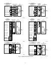
A. OUTDOOR UNIT CONNECTED TO FACTORY-
APPROVED INDOOR UNIT
Factory refrigerant charge is for a 15 ft line set. Outdoor unit
contains correct system refrigerant charge for operation with ARI
rated indoor unit. Check refrigerant charge for maximum effi-
ciency. The charge must be adjusted based on the actual line set
length. Add or subtract 0.6 oz/ft for line sets longer or shorter than
15 ft.
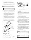
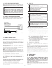
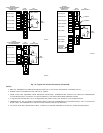
B. INSTALL LIQUID-LINE FILTER DRIER
CAUTION: To avoid performance loss and compressor
failure, installation of filter drier in liquid line is required.
Refer to Fig. 6 and install filter drier as follows:
1. Braze 5-in. connector tube to liquid service valve. Wrap
filter drier with damp cloth.
2. Braze filter drier between connector tube and liquid tube to
indoor coil. Flow arrow must point towards indoor coil.
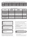
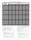
TABLE 1—REFRIGERANT CONNECTIONS AND RECOMMENDED LIQUID AND VAPOR TUBE DIAMETERS (IN.)
UNIT SIZE
LIQUID VAPOR VAPOR (LONG LINE)
Connection Diameter Tube Diameter Connection Diameter Tube Diameter Connection Diameter Tube Diameter
018, 024 3/8 3/8 5/8 5/8 5/8 3/4
030, 036 3/8 3/8 3/4 3/4 3/4 7/8
042, 048 3/8 3/8 7/8 7/8 7/8 1-1/8
060 3/8 3/8 7/8 1-1/8 7/8 1-1/8
NOTES:
1. Tube diameters are forlengths up to50 ft. For tubing lengthsgreater than 50 ft, consultthe Application Guideline and ServiceManual—Air Conditioners and Heat Pumps
Using Puron®.
2. Do not apply capillary tube indoor coils to these units.
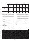
TABLE 2—ACCESSORY USAGE
ACCESSORY
REQUIRED FOR
LOW-AMBIENT
APPLICATIONS
(BELOW 55°F)
REQUIRED FOR
LONG-LINE
APPLICATIONS*
(OVER 50 FT)
REQUIRED FOR
SEA COAST
APPLICATIONS
(WITHIN 2 MILES)
Crankcase Heater Yes Yes No
Evaporator Freeze Thermostat Yes No No
Winter Start Control Yes† No No
Accumulator No No No
Compressor Start Assist
Capacitor and Relay
Yes Yes No
MotorMaster® Control,
or
Low-Ambient Pressure Switch
Yes No No
Wind Baffle See Low-Ambient Instructions No No
Coastal Filter No No Yes
Support Feet Recommended No Recommended
Liquid-Line Solenoid Valve
or
Hard Shutoff TXV
No See Long-Line Application Guideline No
Ball Bearing Fan Motor Yes‡ No No
* For Tubing Sets between 50 and 175 ft horizontal or 20 ft vertical differential, refer to the Application Guideline and Service Manual—Air Conditioners and Heat Pumps
Using Puron®.
† Only when low-pressure switch is used.
‡ Required for low-ambient controller (full modulation feature) and MotorMaster® Control only.
—4—