


4
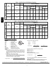
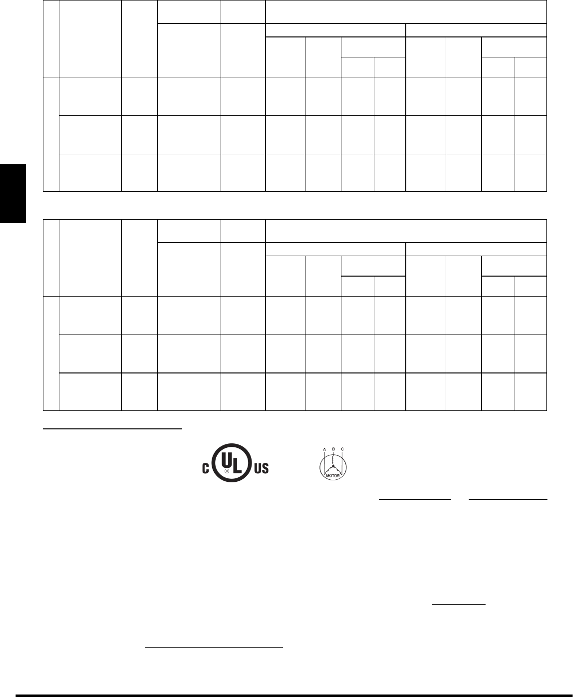
Table 1 – Unit Wire/Fuse or HACR Breaker Sizing Data
UNIT
NOM.
V --- Ph --- H z
IFM
TYPE
COMBUSTION
FAN MOTOR
POWER
EXHA UST
NO C.O. or UNPWR C.O.
FLA FLA
NO P.E. w/ P.E. (pwrd fr/ unit)
MCA
FUSE
or
HACR
BRKR
DISC. SIZE
MCA
FUSE
or
HACR
BRKR
DISC. SIZE
FLA LRA FLA LRA
580J*16D
208/230---3---60
STD
0.48 3.8
68.3 80 71 396 72.1 80 76 400
MED 70.8 80 74 413 74.6 90 79 417
HIGH 77.8/75.8 100/100 82/80 424 81.6/79.6 100/100 87/84 428
4 60 --- 3 --- 6 0
STD
0.25 1.8
34.0 45 35 234 35.8 45 37 236
MED 35.0 45 37 243 36.8 45 39 245
HIGH 38.2 50 40 248 40.0 50 42 250
5 75 --- 3 --- 6 0
STD
0.24 3.8
26.5 30 28 184 30.3 40 32 188
MED 26.5 30 28 184 30.3 40 32 188
HIGH 29.8 35 31 187 33.6 40 36 191
Table 1 — Unit Wire/Fuse or HACR Breaker Sizing Data (cont)
UNIT
NOM.
V --- Ph --- H z
IFM
TYPE
COMBUSTION
FAN MOTOR
POWER
EXHA UST
w/ PWRD C.O.
FLA FLA
NO P.E. w/ P.E. (pwrd fr/ unit)
MCA
FUSE
or
HACR
BRKR
DISC. SIZE
MCA
FUSE
or
HACR
BRKR
DISC. SIZE
FLA LRA FLA LRA
580J*16D
208/230---3---60
STD
0.48 3.8
73.1 80 77 401 76.9 100 81 405
MED 75.6 100 80 418 79.4 100 84 422
HIGH 82.6/80.6 100/100 88/85 429 86.4/84.4 100/100 92/90 433
4 60 --- 3 --- 6 0
STD
0.25 1.8
36.2 45 38 236 38.0 50 40 238
MED 37.2 50 39 245 39.0 50 41 247
HIGH 40.4 50 43 250 42.2 50 45 252
5 75 --- 3 --- 6 0
STD
0.24 3.8
28.2 35 30 186 32.0 40 34 190
MED 28.2 35 30 186 32.0 40 34 190
HIGH 31.5 40 33 189 35.3 45 38 193
Legend and Notes for Table 1
LEGEND:
BRKR --- Circuit breaker
CO --- Convenience outlet
DISC --- Disconnect
FLA --- F ull load amps
IFM --- Indoor fan motor
LRA --- Locked rotor amps
MCA --- Minimum circuit amps
P E --- Pow er e xh au st
PWRD CO --- Powered convenient outlet
UNPWR CO --- Unpowered convenient outlet
NOTES:
1. In compliance with NEC requirements for multimotor and
combination load equipment (refer to NEC Articles 430 and
440), the overcurrent protective device for the unit shall be
fuse or HACR breaker. Canadian units may be fuse or circuit
breaker.
2. Unbalanced 3-Phase Supply Voltage
Never operate a motor where a phase imbalance in supply
voltage is greater than 2%. Use the following formula to d e-
termine the percentage of voltage imbalance.
% Volta ge Imbalance =100 x
max voltage deviatio n from average voltage
average voltage
Example: Supply voltage is 230-3-60
AB = 224 v
BC = 231 v
AC = 226 v
Average Voltage =
(224 + 231 + 226)
=
681
3
3
= 227
Determine maximum deviation from average voltage.
(AB) 227 – 224 = 3 v
(BC) 231 – 227 = 4 v
(AC) 227 – 226 = 1 v
Maximum deviation is 4 v.
Determine percent of voltage imbalance.
% Volta ge Imbalance = 100 x
4
227
= 1.76%
This amount of phase imbalance is satisfactory as it is below the
maximum allowable 2%.
IMPORTANT: If the supp ly voltage phase imbalance is more than
2%, contact your local electric utility company immediately.
2011 Bryant Heating and Cooling Systems. D 7310 W. Morris St. D Indianapolis, IN 46231 Printed in U.S.A. Edition Date: 01/11
Manufacturer res er ves the r ight to change, at any time, specifications and designs without notice and without obligations.
Catalog No: SS580J---02
Replaces: New
580J*16D