


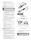
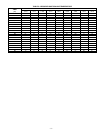

2. Braze filter drier between connector tube and liquid tube to
indoor coil. Flow arrow must point towards indoor coil.
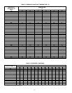
C. REFRIGERANT TUBING
Connect vapor tube to fitting on outdoor unit vapor service valves.
Connect liquid tube to filter drier. (See Fig. 6 and Table 1.) Use
refrigerant grade tubing.
D. SWEAT CONNECTION
CAUTION: To avoid valve damage while brazing, ser-
vice valves must be wrapped in a heat-sinking material
such as a wet cloth.
Service valves are closed from factory and ready for brazing. After
wrapping service valve and filter drier with a wet cloth, tubing set
can be brazed to service valve and filter drier using either silver
bearing or non-silver bearing brazing material. Consult local code
requirements. Refrigerant tubing and indoor coil are now ready for
leak testing. This check should include all field and factory joints.
E. EVACUATE REFRIGERANT TUBING AND INDOOR
COIL
CAUTION: Never use the system compressor as a
vacuum pump.
Refrigerant tubes and indoor coil should be evacuated using the
recommended deep vacuum method of 500 microns. The alternate
triple evacuation method may be used if the procedure outlined
below is followed. Always break a vacuum with dry nitrogen.
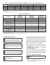
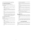
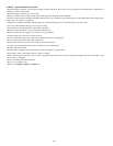
DEEP VACUUM METHOD
The deep vacuum method requires a vacuum pump capable of
pulling a vacuum of 500 microns and a vacuum gage capable of
accurately measuring this vacuum depth. The deep vacuum
method is the most positive way of assuring a system is free of air
and liquid water. (See Fig. 7.)
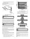
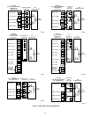
TRIPLE EVACUATION METHOD
The triple evacuation method should only be used when vacuum
pump is only capable of pumping down to 28 in. of mercury
vacuum and system does not contain any liquid water. Refer to
Fig. 8 and proceed is as follows:
1. Pump system down to 28 in. of mercury and allow pump to
continue operating for an additional 15 minutes.
2. Close service valves and shut off vacuum pump.
3. Connect a dry nitrogen cylinder and regulator to system and
open until system pressure is 2 psig.
4. Close service valve and allow system to stand for 1 hr.
During this time, dry nitrogen will be able to diffuse
throughout the system absorbing moisture.
5. Repeat this procedure as indicated in Fig. 8. System will
then be free of any contaminants and water vapor.
VIII. MAKE ELECTRICAL CONNECTIONS
WARNING: To avoid personal injury or death, do not
supply power to unit with compressor terminal box cover
removed.
Be sure field wiring complies with local and national fire, safety,
and electrical codes, and voltage to system is within limits shown
on unit rating plate. Contact local power company for correction of
improper voltage. See unit rating plate for recommended circuit
protection device.
NOTE: Operation of unit on improper line voltage constitutes
abuse and could affect unit reliability. See unit rating plate. Do not
install unit in system where voltage may fluctuate above or below
permissible limits.
NOTE: Use copper wire only between disconnect switch and
unit.
Fig. 6—Liquid-Line Filter Drier
A95509
LIQUID-LINE
FILTER-DRIER
CONNECTOR
TUBE
R
-
4
1
0
A
LIQUID
SERVICE
VALVE
Fig. 7—Deep Vacuum Graph
A95424
500
MINUTES
01234567
1000
1500
LEAK IN
SYSTEM
VACUUM TIGHT
TOO WET
TIGHT
DRY SYSTEM
2000
MICRONS
2500
3000
3500
4000
4500
5000
A95424
Fig. 8—Triple Evacuation Method
A95425
CHECK FOR TIGHT, DRY SYSTEM
(IF IT HOLDS DEEP VACUUM)
EVACUATE
BREAK VACUUM WITH DRY NITROGEN
WAIT
EVACUATE
CHARGE SYSTEM
BREAK VACUUM WITH DRY NITROGEN
EVACUATE
WAIT
—5—