


7
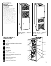
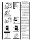
3. Remove air filter from furnace.
• AIR FILTER LOCATED IN
BLOWER COMPARTMENT:
a) Slide filter retainer sideways un-
til it is free of latch. (See Fig. 24)
b) Gently remove air filter and
carefully turn the dirty side up
(if dirty) to avoid spilling dirt
from the filter. (see Fig. 25)
• AIR FILTER LOCATED IN FIL-
TER CABINET:
a) Slide air filter out of furnace.
Keep dirty side up (if dirty) to
avoid spilling dirt. (See Fig. 32
and 33)
26
4. Inspect the filter. If torn, replace it.
NOTE:
If washable filter that was
shipped with the furnace has been re-
placed by:
a) Factory specified disposable
media filter – Do not clean. If
dirty, replace only with media
filter having the same part num-
ber and size. Install with airflow
direction arrow pointing to-
wards blower.
b) Electronic air cleaner (EAC) –
Refer to EAC owner’s Manual
for maintenance information.
5. Wash filter (if dirty) in sink, bath-
tub, or outside with a garden hose.
Always use cold tap water. A mild
liquid detergent may be used if nec-
essary. Spray water through filter in
the opposite direction of airflow.
Allow filter to dry.
6. Reinstall clean air filter
7. Reinstall filter retainer (for blower
compartment locations only)
8. Replace control and blower doors
(See Fig. 16 and 17) or filter cabinet
door (Fig. 34 and 35)
9. Turn on electrical supply to furnace
(see Fig 18).
NOTE:
For upflow models only—if
side return ducts are used, 2 filters may
be required in some models. The pro-
cedure listed above may be used to
remove side filters.
27 28
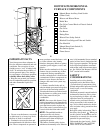
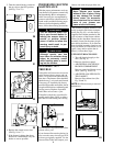
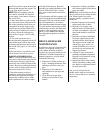
DOWNFLOW/HORIZONTAL
FURNACES ONLY
:
Two filters are located in the return-air
plenum above the blower (above line-
of-sight) resting in the V-shaped chan-
nel on top of the furnace. (See Fig. 27.)
1. Turn OFF electrical supply to the
furnace. (See Fig. 21.)
2. Remove blower access door after
removing 2 screws.
3. Remove the left-side filter by tip-
ping the filter toward the center—
raise it from the V-shaped channel in
which it rests. (See Fig. 27 and 28.)
4. Lower filter down along side of the
blower and remove from the furnace.
5. To remove the second filter, lift
from V-shaped channel and remove
the same way as left side filter.
6. Inspect the filters. If torn, replace
the filter.
7. Wash the filters (if dirty) in a sink,
bathtub, or outside with a garden
hose. Always use cold tap water. A
mild liquid detergent may be used
if necessary. Spray water through
the filter in the opposite direction of
airflow. Allow filter to dry.
8. Reinstall clean filters.
9. Replace blower door (secure with 2
screws) and turn ON electrical
power to your furnace.
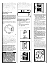
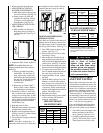
UPFLOW FURNACE
AIR FILTER TABLE
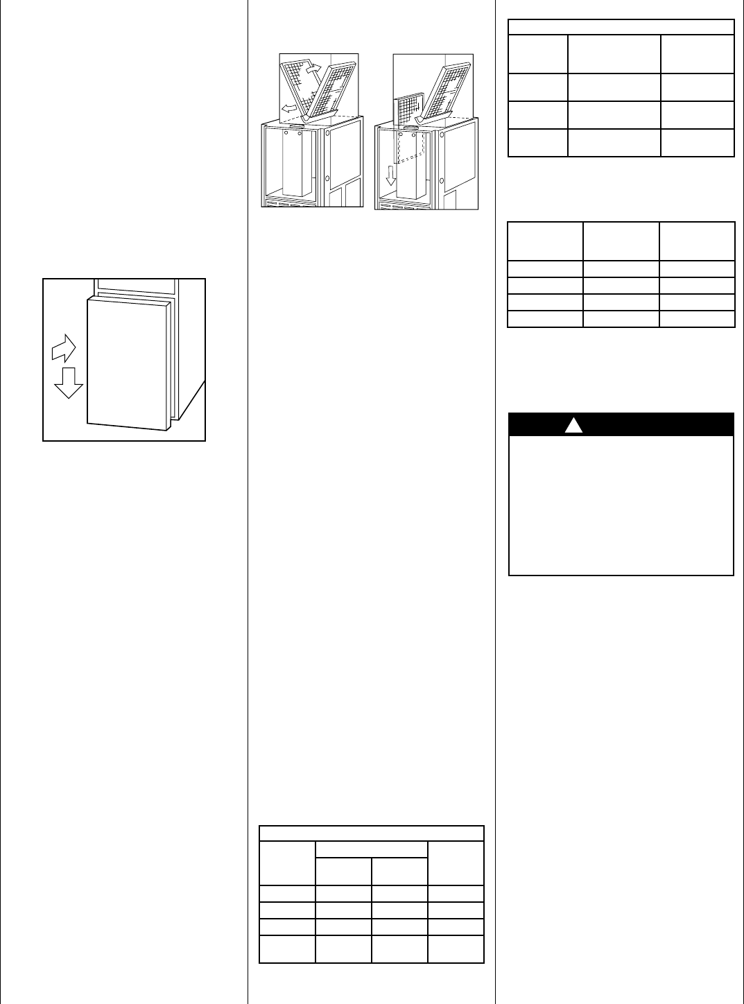
DOWNFLOW/HORIZONTAL
FURNACE FILTER TABLE
*
Factory provided with the furnace.
Filters may be field modified by cutting filter
material and support rods (3) in filters. Alternate
sizes and additional filters may be ordered from
your dealer.
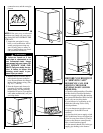
COMBUSTION AREA
AND VENT SYSTEM
Inspect the combustion area and vent
system before each heating season. An
accumulation of dirt, soot, or rust can
mean a loss of efficiency and improper
performance. Buildups on the main
burners can cause faulty firing. This
“delayed ignition’’ is characterized by
an alarmingly loud sound. If your fur-
nace makes a loud noise when the main
burners are ignited, shut down the fur-
nace—call your servicing dealer.
Use your flashlight and follow these
steps for inspecting the combustion
area and vent system of your furnace:
1. Turn off the electrical supply to the
furnace and remove the access
doors. (See Fig. 9 and 10, or 11.)
2. Carefully inspect the gas burner
(see Fig. 29) for dirt, rust, or scale.
Then inspect the relief box, flue
AIR FILTER LOCATED IN BLOWER COMPARTMENT
FURNACE
CASING
WIDTH
FILTER SIZE (IN.)
FILTER
TYPESide Return
Bottom
Return
14-3/16 (1)16x25x1* (1)14x25x1* Cleanable
17-1/2 (1)16x25x1* (1)16x25x1** Cleanable
21 (1)16x25x1* (1)20x25x1* Cleanable
24-1/2
(1 or 2)
16x25x1 (1)24x25x1** Cleanable
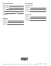
AIR FILTER LOCATED IN FILTER CABINET
FILTER
CABINET
HEIGHT (IN)
FILTER SIZE
(IN.) FILTER TYPE
16
(1) 16 x 25 x 1* or
(1) 16 x 25 x 4-5/16
Cleanable
Disposable
20
(1) 20 x 25 x 1* or
(1) 20 x 25 x 4-5/16
Cleanable
Disposable
24
(1) 24 x 25 x 1* or
(1) 24 x 25 x 4-5/16
Cleanable
Disposable
FURNACE
CASING
WIDTH FILTER SIZE
FILTER
TYPE
14-3/16 (2)16x20x1* Cleanable
17-1/2 (2)16x20x1* Cleanable
21 (2)16x20x1* Cleanable
24-1/2 (2) 16x20x1* Cleanable
CAUTION
Use care when cutting support
rods in filters to protect
against flying pieces and
sharp rod ends. Wear safety
glasses, gloves, and appropri-
ate protective clothing. Failure
to follow this caution could re-
sult in personal injury.
!