3
2. Drop three ice cubes into a glass of water and stir. If, within
three minutes, moisture does not form on the glass, the air is
too dry and a humidifier would be beneficial. (Do not per-
form this test in the kitchen, cooking vapors may produce
inaccurate results.)
A good relative humidity is one just high enough to barely start
condensation along the lower edges or lower corners of the
windows, when it is cold outside. More than that can be damaging.
If the humidity is too high, try these suggestions to lower the
humidity:
1. Reduce setting or discontinue use of humidifier .
2. Use range and bathroom exhaust fans while cooking and
bathing. Open a door or window for a few minutes to bring
in cool drier air.
3. Cook with pans covered.
4. Take shorter baths or showers with cooler water.
5. Install a fresh air intake duct. Cold, dry air brought in from
outside to the furnace area lowers the indoor humidity level.
6. Have appliances checked. A malfunctioning appliance can
contribute water vapor to the structure.
7. If the problem continues, consult a heating contractor about
adding a heat recovery ventilator or air--to--air heat ex-
changer.
About Your Furnace
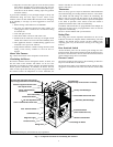
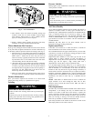
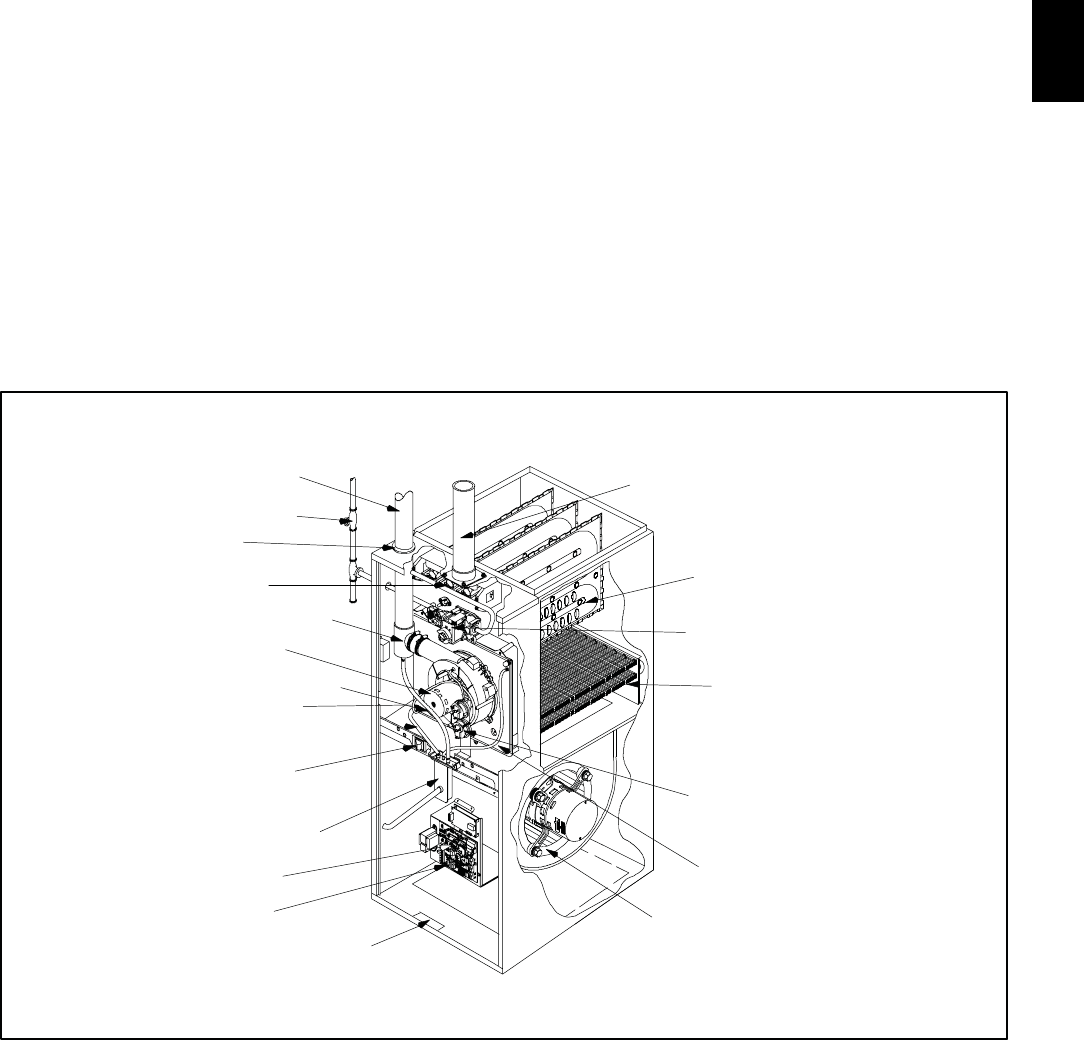
Fig. 2 shows the location of the components in the furnace.
Circulating Air Blower
The b lower circulates room air through the furnace, air ducts, and
into the rooms of the structure. The blower can be set at the
thermostat for automatic or manual operation. In manual mode the
blower operates continuously. In automatic, the blower does not
come on until a preset time after the gas valve is energized. When
the structure reaches the temperature set on the thermostat, the
furnace will shut off. The blower will continue to run until the
furnace cools down.
Thermostat
There are many types and styles of thermostats. Most thermostats
control both heating and cooling functions and have a Fan Switch
with AUTO and ON settings. On AUTO, the Circulating Air
Blower will cycle on/off with the furnace on the heating speed
unless a call f or cooling is initiated. Blower speed will correspond
to the mode of operation of the furnace. If the Fan Switch is
positioned to ON the blower will run continuously.
In addition s ome thermostats are programmable with multiple set
backs. The set backs can be pre--programmed to lower or raise the
temperature automatically.
Be sure to become familiar with your thermostat.
Rating Plate
The rating plate contains important information for the service
technician and lists the complete model, manufacturing and serial
numbers. You should always provide all these numbers when
requesting parts or if you need service. See Fig. 2 for rating plate
location.
Door Interlock Switch
All the electrical power for the furnace goes through the door
interlock switch. The interlock switch interrupts electrical power to
the furnace when the blower door is removed. The furnace will not
operate until the blower door is reinstalled.
Furnace Control
The furnace control provides power to the circulating air blower to
keep it on until the furnace cools down.
The fan off--delay setting can be adjusted if the fan remains on long
enough that cool drafts are felt in the room after the furnace shuts
off.
Manual Equipment Shutoff Valve
Primary Heat Exchanger
Circulating Air Blower
Furnace Control
Pressure Switches
(some models have one)
Representative drawing only, some models may vary in appearance.
Air Intake Pipe
(Required only for Direct--Vent Furnaces)
Rating Plate
Secondary
Heat Exchanger
Furnace Main Gas Control Valve
Plastic Transition Box
Door Interlock Switch
Condensate Trap
5
/
8
″
I.D. Transition Box Drain Hose
1
/
2
″
I.D. Vent Pipe Drain Hose
Combustion Blower
Vent Drain Fitting
Vent Pipe Grommet
Furnace Vent Pipe (Vent Pipe Connec-
tions through Side Panel on Some Models-
Diagnostic Light
Ignitor & Flame Sensor
(not shown)
A07689
Fig. 2 -- Component Locations for Condensing 90+ Furnaces
359BAV


