


9
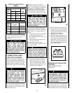
FURNACE AIR FILTER
TABLE
* Factory-provided with the furnace. Filters may be
field modified by cutting filter material and support
rods (3) in filters. Alternate sizes and additional fil-
ters may be ordered from your dealer.
† Upflow only.
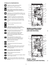
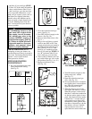
COMBUSTION AREA
AND VENT SYSTEM
Visually inspect the combustion area
and vent system before each heating
season. Make sure that all PVC pipes
leading into the combustion area and
vent are free from any cracks and sags.
Also check the combustion-air intake
and vent pipes on the outside of your
home for blockage.
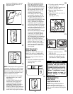
When dirt, soot, scale, or rust is
allowed to build up, your furnace can
suffer a loss of efficiency and perform
improperly. Accumulations on the
main burners can result in firing out of
normal sequence. This delayed igni-
tion creates an alarmingly loud sound.
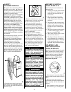
To inspect the combustion area and
vent system, you will need a flashlight.
Refer to Fig. 3 or 4, and proceed as
follows:
1. Turn off gas and electrical supplies
to the furnace and remove
the main furnace door. (See Fig. 9,
10, and 11.)
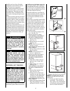
2. Remove burner enclosure front.
(See Fig. 37 or 38.)
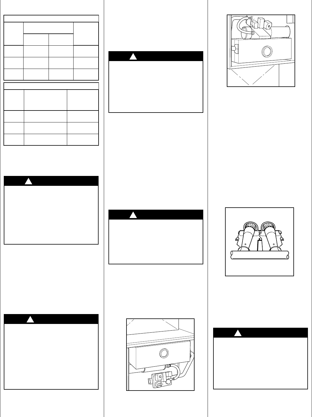
Inspect the gas burners, igniter
area, and remainder of furnace for dirt,
rust, soot, or scale.
3. Inspect the combustion-air and
vent PVC pipes for sags, holes,
cracks, or disconnections. Hori-
zontal portions of pipes must slope
downward toward furnace.
37
38
4. Reinstall burner enclosure front.
5. If your furnace is free of the above
conditions, replace main furnace
door and turn on electrical and gas
supplies to your furnace.
(See Fig. 16, 17, and 18.)
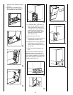
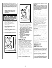
6. Start the furnace and observe its
operation. Watch the burner flames
to see if they are clear blue, almost
transparent. (See Fig. 39.) If you
observe a suspected malfunction,
or the burner flames are not clear
blue, call your dealer.
39
HEADING SOUTH FOR THE
WINTER?
DON’T FORGET YOUR
FURNACE!
Since the furnace uses a condensing
heat exchanger, some water will accu-
mulate in the unit as a result of the heat
AIR FILTER LOCATED IN BLOWER COMPARTMENT
FURNACE
CASING
WIDTH
(IN.)
FILTER SIZE
(IN.)
FILTER
TYPE
*Side
Return†
Bottom
Return
17-1/2 (1) 16 x
25 x 1*
(1) 16 x
25 x 1*
Cleanable
21 (1) 16 x
25 x 1
(1) 20 x
25 x 1*
Cleanable
24-1/2 (1 or 2) 16
x 25 x 1
(1) 24 x
25 x 1*
Cleanable
AIR FILTER LOCATED IN FILTER CABINET:
FILTER
CABINET
HEIGHT
(IN)
FILTER SIZE
(IN.) FILTER TYPE
16 (1) 16 x 25 x 1*
or (1) 16 x 25 x 4-5/16
Cleanable or
Disposable
20 (1) 20 x 25 x 1*
or (1) 20 x 25 x 4-5/16
Cleanable or
Disposable
24 (1) 24 x 25 x 1*
or (1) 24 x 25 x 4-5/16
Cleanable or
Disposable
CAUTION
Use care when cutting support
rods in filters to protect
against flying pieces and
sharp rod ends. Wear safety
glasses, gloves, and appropri-
ate protective clothing. Failure
to follow this caution could re-
sult in personal injury.
DANGER
If holes are found in the pipes
or if any portion has become
disconnected, toxic fumes
can escape into your home.
DO NOT OPERATE YOUR
FURNACE. Call your dealer for
service. Failure to follow this
warning could result in per-
sonal injury or death.
!
!
CAUTION
If your furnace makes an espe-
cially loud noise when the
main burners light, shut down
your furnace and call your
dealer. Failure to follow this
caution would result in minor
property damage.
CAUTION
If dirt, rust, soot, or scale accu-
mulations are found, call your
dealer. Do not operate your
furnace. Failure to follow this
caution would result in minor
property or product damage.
!
!
UPFLOW
CAUTION
If the furnace is installed in an
unconditioned space where
the ambient temperatures may
be 32°F or lower, freeze protec-
tion measures must be taken
to prevent minor property or
product damage.
DOWNFLOW
!