


9
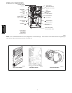
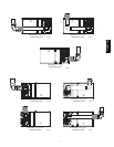
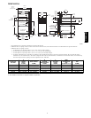
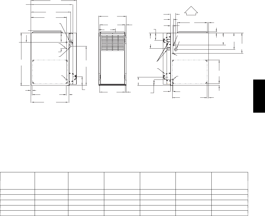
DIMENSIONS
2-7/16"
1-1/8"
28-7/8"
(733mm)
25-1/4"
22-9/16"
JUNCTION BOX
LOCATION
7/8" DI A
ACCESSORY
1/2" (13 mm) DIA.
THERMOSTAT WIRE ENTRY
3-15/16" (84mm)
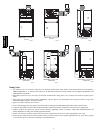
LEFT HAND GAS
ENTRY
33-5/16"
24-7/8"
5-1/2"
7/8" (22mm) DIA.
ACCESSORY
11/16"
21-5/8"
BOTTOM INLE T
1-11/16"
13/16"
11/16"
4-13/16"
AIRFLOW
19"
OUTLE T
13/16"
11/16"
8-9/16"
VENT OUTLE T
5 PLACES (TYP)
3-3/4"
1-3/4" DIA.RIGHT HAND
GAS ENTRY
7/8" DIA. K.O. WIRE ENTRY
SIDE INLE T
14-7/8"
7/8" DIA. ACCESSORY
1-1/4"
1"
22-1/16"
A
D
F
E
(FLUE COLLAR)
5-15/16"
(135mm)
24"
CASING
1-5/16"
1/2" DIA. K.O.THERMOSTAT
WIRE ENTRY
ALTERNAT E
JUNCTION BOX
LOCATIONS (TYP)
26-1/8"
1-1/2"
7-3/4"
9-5/8"
11-1/2"
5-1/2"
(664mm)
(641mm)
(573mm)
(22mm)
(846mm)
(17mm)
(549mm)
(
610mm
)
(43mm)
(140mm)
(632mm)
(17mm)
(140mm)
(95mm)
(21mm)
(122mm)
(217mm)
(62mm)
(33mm)
(29mm)
(483mm)
(13mm)
(44mm)
(22mm)
(22mm)
(38mm)
(560mm)
(25mm)
(32mm)
(378mm)
(17mm)
(197mm)
(244mm)
(292mm)
(21mm)
A04037
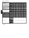
1. Two additional 7/8--in. (22 mm) dia. knockouts are located in the top plate.
2. Minim um return-- air openings at f urnace, based on metal d uct. If flex duct is used, see flex duct manuf actu r er’s recommendations for equivalent diameters.
3. Minim um return--air opening at furnace.
a. For 800 CFM --16--in. (406 mm) round or 14--1/2 x 12--in. (368 x 305 mm) rectangle.
b. For 1200 CFM--20 --in. (508 mm) round or 14--1/2 x 19 --1/3 in. (368 x 491 mm)rectangle.
c. For 1600 CFM --22--in. (559 mm) round or 14--1/2 x 22--1/16 --in. (368 x 560 mm) rectangle.
d. For airflow requirements above 1800 CFM,see Air Delivery table in Product Data literature for specific use of single side inlets. The use of both side inlets, a
combination of 1 side and the bottom, or the bottom of single side inlets. The use of both side inlets, a combination of one side and the bottom, or the bottom only
will ensure adequate return air openings for airflow requirements above 1800 CFM.
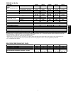
313AAV/JA V
UNIT SIZE
A
CABINET
WIDTH
IN (MM)
D
SUPPLY WIDTH
IN (MM)
E
BOTTOM
RETURNWIDTH
IN (MM)
F
TOP VENT
OUTLET
IN (MM)
VENT
CONNECTION
SIZE
(see Notes 1 & 2)
MEDIA CABINET
SIZE
IN (MM)
024045 14---3/16 (360) 12---9/16 (319) 12---11/16 (322) 9---5/16 (237) 4 16 (406)
048070 17---1/2 (445) 15---7/8 (403) 16---1/8 (410) 11---9/16 (294) 4 16 (406)
048090 21 (533) 19---3/8 (492) 19---1/2 (495) 13---5/16 (338) 4 20 (508)
060110 21 (533) 19---3/8 (492) 19---1/2 (495) 13---5/16 (338) 4 20 (508)
060135 24---1/2 (622) 22---7/8 (581) 23 (584) 15---1/16 (383) 4(Note1) 24 (610)
1. 135 size furnaces require 5---in. (127 mm) ven ts. Use a 4---5 in. (102---127 mm) vent adaptor between furnace and vent stack.
2. See installation instructions for complete installation requirements.
313AAV/JAV