


18
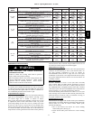
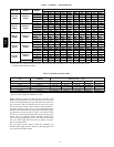
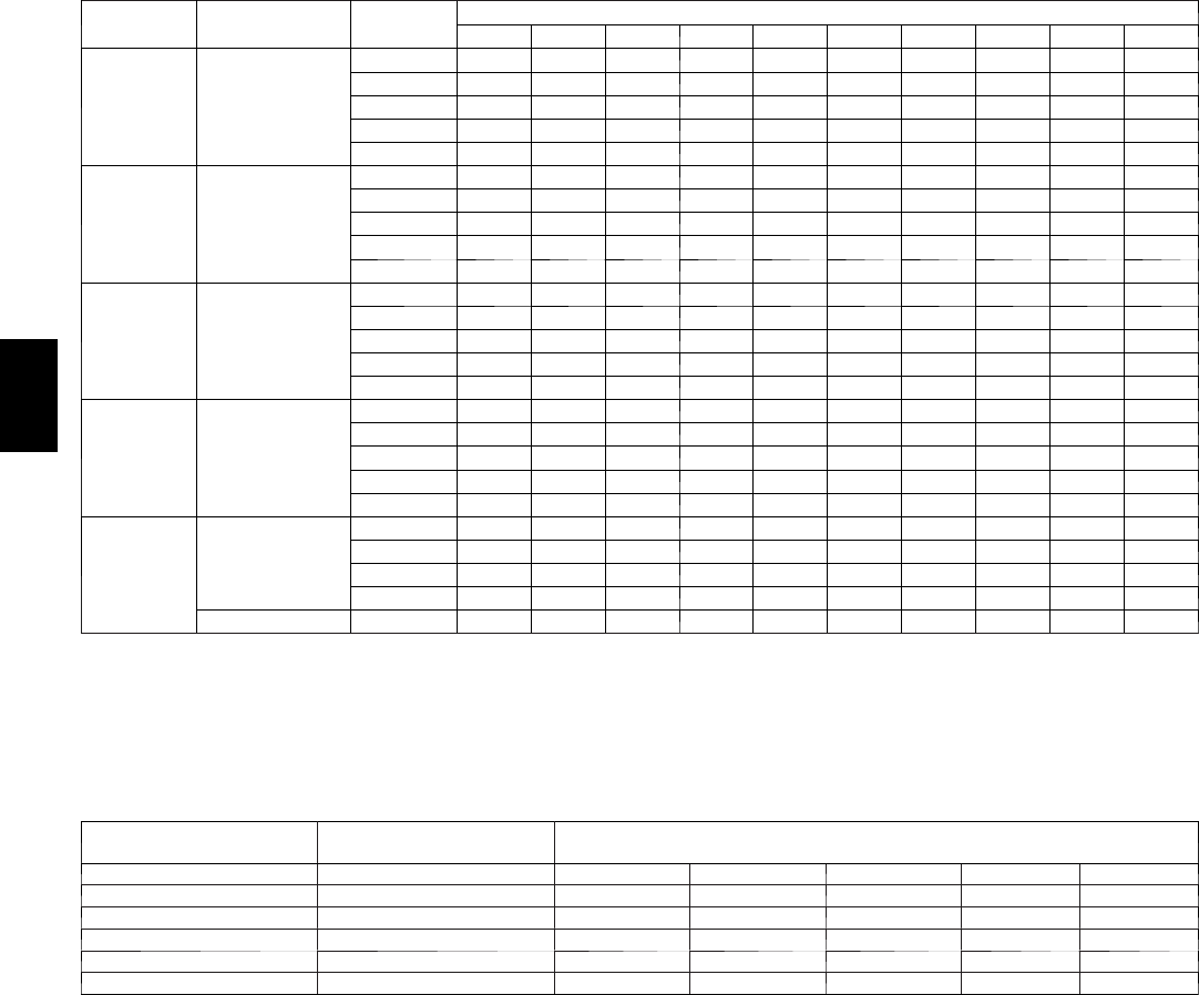
Table 5 – Air Delivery -- CFM (With Filter)*
UNIT SIZE
RETURN---AIR
SUPPLY
SPEED
EXTERNAL STATIC PRESSURE (In. wc)
0.1 0.2 0.3 0.4 0.5 0.6 0.7 0.8 0.9 1
045---08/
024045
Bottom or
Side(s)
5 1185 1145 1115 1075 1035 980 905 820 720 580
4 920 880 835 800 755 720 680 645 605 540
3 735 685 625 585 530 490 435 395 345 295
2 820 765 725 670 630 580 545 490 455 405
1 650 595 535 490 430 390 330 280 235 --- ---
070---16 /
048070
Bottom or
Side(s)
5 1625 1585 1535 1495 1460 1415 1365 1295 1220 1125
4 1405 1360 1320 1280 1240 1195 1155 1115 1070 1030
3 1240 1200 1155 1110 1065 1020 975 935 895 850
2 1190 1140 1095 1050 1000 955 915 870 830 790
1 1035 985 930 885 835 785 745 695 650 600
090---16 /
048090
Bottom or
Side(s)
5 1845 1800 1755 1710 1665 1595 1500 1400 1275 1105
4 1590 1545 1500 1455 1410 1365 1315 1270 1180 1000
3 1365 1320 1270 1215 1170 1125 1070 1025 955 900
2 1225 1160 1110 1060 1010 950 895 830 770 710
1 1100 1030 960 875 805 730 645 570 505 425
110---20 /
060110
Bottom or
Side(s)
5 2255 2205 2150 2100 2040 1985 1920 1835 1735 1615
4 1600 1525 1465 1400 1335 1275 1210 1150 1080 1015
3 1945 1890 1830 1770 1715 1655 1600 1545 1480 1430
2 1420 1340 1280 1200 1140 1065 1005 925 865 790
1 1280 1205 1140 1055 990 910 840 760 695 630
135---20 /
060135
Bottom or
Side(s)
5 2295 2240 2185 2125 2070 2005 1925 1805 1670 1545
4 1725 1660 1605 1545 1460 1395 1340 1285 1230 1170
3 1910 1865 1800 1745 1685 1610 1545 1485 1435 1380
2 1630 1575 1510 1435 1365 1300 1245 1185 1130 1065
1 1430 1355 1285 1200 1125 1075 1015 945 855 800
*A filter is required for each return---air inlet. Airflow performance included 3/4---in. (19 mm) washable filter media such as contained in factory--- authorized
accessory filter rack. To determine airflow performance without this filter, assume an additional 0.1 in. wc available external static pressure.
------ Indicates unstable operating conditions.
Table 6 – Maximum Capacity of Pipe*
NOMINAL IRON
PIPE
INTERNAL
DIAMETER
LENGTH OF PIPE --- FT. (M)
SIZE IN. (mm) In. (mm) 10 20 30 40 50
1/2 (13) 0.622 (16) 175 (53) 120 (37) 97 (30) 82 (25) 73 (22)
3/4 (19) 0.824 (21) 360 (110) 250 (76) 200 (61) 170 (52) 151 (46)
1 (25) 1.049 (27) 680 (207) 465 (142) 375 (114) 320 (98) 285 (87)
1---1/4 (32) 1.380 (35) 1400 (427) 950 (290) 770 (235) 660 (201) 580 (177)
1---1/2 (38) 1.610 (41) 2100 (640) 1460 (445) 1180 (360) 990 (301) 900 (274)
* Cubic ft. of natural gas per hr for gas pressures of 0.5 psig (14---in. wc) or less and a pressure drop of 0.5---in wc (based on a 0.60 specific gravity
gas). Ref: Chapter 6 ANSI Z223---2006/NFPA 54---2006.
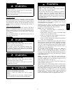
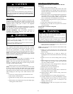
Piping should be pressure and leak tested in accordance with
NFGC in the United States or CAN/CSA-- B149.1 --05 in Canada,
local, and national plumbing and gas codes before the furnace has
been connected. After all connections have been made, purge
lines and c heck for leakage at furnace prior to operating f urnace.
If pressure exceeds 0.5 psig (14--in. wc), gas s upply pipe must be
disconnected from furnace and capped before and during supply
pipe pressure test. If test pressure is equal to or less than 0.5 psig
(14-- in. wc), turn off electric shutoff switch located on furnace gas
control valve and accessible manual equipment shutoff valve
before and during supply pipe pressure test. After all connections
have been made, purge lines and check for leakage at furnace
prior t o operating furnace.
The gas supply pressure shall be within the maximum and
minimum inlet supply pressures marked on the rating plate with
the furnace burners ON and OFF.
313A