


7
Check Charge
Factory charge amount and desired subcooling are shown on unit
rating plate. Charging method is shown on information plate inside
unit. To properly check or adjust charge, conditions must be
favorable for subcooling charging. Favorable conditions exist
when the outdoor temperature is between 70_F and 100_F
(21.11_C and 37.78_C), and the indoor temperature is between
70_F and 80_F (21.11_C and 26.67_C). Follow the procedure
below:
Unit is factory charged for 15ft (4.57 m) of lineset. Adjust charge
by adding or removing 0.6 oz/ft (.018 kg/m) of 3/8 liquid line
above or below 15ft (4.57 m) respectively.
For standard refrigerant line lengths (80 ft/24.38 m or less), allow
system to operate in cooling mode at least 15 minutes. If conditions
are favorable, check system charge by subcooling method. If any
adjustment is necessary, adjust charge slowly and allow system to
operate for 15 minutes to stabilize before declaring a properly
charged system.
If the indoor temperature is above 80_F (26.67_C), and the
outdoor temperature is in the favorable range, adjust system charge
by weight based on line length and allow the indoor temperature to
drop to 80_F (26.67_C) before attempting to check system charge
by subcooling method as described above.
If the indoor temperature is below 70_F (21.11_C), or the outdoor
temperature is not in the favorable range, adjust charge for line set
length above or below 15ft (4.57 m) only. Charge level should then
be appropriate for the system to achieve rated capacity. The charge
level could then be checked at another time when the both indoor
and outdoor temperatures are in a more favorable range.
NOTE: If line length is beyond 80 ft (24.38 m) or greater than 20
ft (6.10 m) vertical separation, See Long Line Guideline for
special charging requirements.
Units with Cooling Mode TXV
Units installed with cooling mode TXV require charging by the
subcooling method.
1. Operate unit a minimum of 10 minutes before checking
charge.
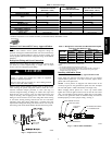
2. Measure liquid service valve pressure by attaching an accur-
ate gage to service port.
3. Measure liquid line temperature by attaching an accurate
thermistor type or electronic thermometer to liquid line near
outdoor coil.
4. Refer to unit rating plate for required subcooling temperat-
ure.
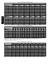
5. Refer to Table 3. Find the point where required subcooling
temperature intersects measured liquid service valve pres-
sure.
6. To obtain required subcooling temperature at a specific li-
quid line pressure, add refrigerant if liquid line temperature
is higher than indicated or reclaim refrigerant if temperature
is lower. Allow a tolerance of 3_F.
Units with Indoor Pistons
Units installed with indoor pistons require charging by the
superheat method.
The following procedure is valid when indoor airflow is within
21 percent of its rated CFM.
1. Operate unit a minimum of 10 minutes before checking
charge.
2. Measure suction pressure by attaching an accurate gage to
suction valve service port.
3. Measure suction temperature by attaching an accurate ther-
mistor type or electronic thermometer to suction line at ser-
vice valve.
4. Measure outdoor air dry--bulb temperature with thermomet-
er.
5. Measure indoor air (entering indoor coil) wet--bulb temper-
ature with a sling psychrometer.
6. Refer to Table 4. Find outdoor temperature and evaporator
entering air wet--bulb temperature. At this intersection, note
superheat. Where a dash (----) appears on the table, do not
attempt to charge system under these conditions or refriger-
ant slugging may occur. Charge must be weighted in,
adding or removing 0.6 oz/ft of 3/8 liquid line above or be-
low 15 ft (4.57 m) respectively.
7. Refer to Table 5. Find superheat temperature located in item
6 and suction pressure. At this intersection, note suction line
temperature.
8. If unit has a higher suction line temperature than charted
temperature, add refrigerant until charted temperature is
reached.
9. If unit has a lower suction line temperature than charted
temperature, reclaim refrigerant until charted temperature is
reached.
10. When adding refrigerant, charge in liquid form into suction
service port using a flow--restricting device.
11. If outdoor air temperature or pressure at suction valve
changes, charge to new suction line temperature indicated
on chart.
12. Optimum performance will be achieved when the operating
charge produces 5_ to 6_F suction superheat at suction
service valve with 82_F outdoor ambient and 80_F
(26.7_C) dry bulb (67_F / 19.4_C) wet bulb) indoor
temperature (DOE “B” test conditions) at rated airflow.
Heating Check Chart Procedure
To check system operation during heating cycle, refer to the
Heating Check Chart on outdoor unit. This chart indicates whether
a correct relationship exists between system operating pressure and
air temperature entering indoor and outdoor units. If pressure and
temperature do not match on chart, system refrigerant charge may
not be correct. Do not use chart to adjust refrigerant charge.
223A / 225B