


3
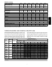
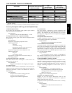
PHYSICAL DATA
UNIT SIZE---VOLTAGE, SERIES 018---D 024---D 030---E 036---E 042---C 048---E 060---F
Operating Weight lb (kg)
107
(48.5)
110
(49.9)
111
(50.3)
141
(64.0)
190
(86.2)
186
(84.4)
190
(86.2)
Shipping Weight lb (kg)
130
(59.0)
134
(60.8)
136
(61.7)
170
(77.1)
218
(98.9)
224
(101.6)
226
(102.5)
Compressor Type Scroll
REFRIGERANT Puron® (R---410A)
Control TXV (Puron® Hard Shutoff)
Charge lb (kg)
3.50
(1.60)
3.80
(1.72)
4.1
(1.86)
5.34
(2.42)
5.84
(2.65)
7.00
(3.18)
8.19
(3.71)
COND FAN Propeller Type, Direct Drive
Air Discharge Vertical
Air Qty (CFM) 1792 2218 2218 2954 3167 3644 3129
Motor HP 1/12 1/10 1/10 1/4 1/5 1/4 1/4
Motor RPM 1100 1100 1100 1100 1100 1100 800
COND COIL
Face Area (Sq ft) 8.4 8.4 9.80 13.13 17.25 19.40 12.93
Fins per In. 20 25 25 25 25 25 20
Rows 1 1 1 1 1 1 2
Circuits 3 3 3 3 4 5 5
VALVECONNECT.(In.ID)
Vapor 3/4 3/4 3/4 7/8 7/8 7/8 1 --- 1/8
Liquid 3/8
REFRIGERANT TUBES (In. OD)
Rated Vapor* 3/4 3/4 7/8 7/8 1 --- 1/8 1 --- 1/8 1 --- 1/8
Liquid 3/8
* Units are rated with 25 ft (7.6 m) of lineset length. See Vapor Line Sizing and Cooling Capacity Loss table when using other sizes and lengths of lineset.
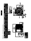
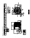
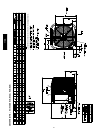
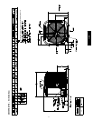
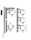
Note: See unit Installation Instruction for proper installation.
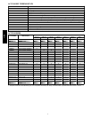
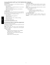
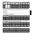
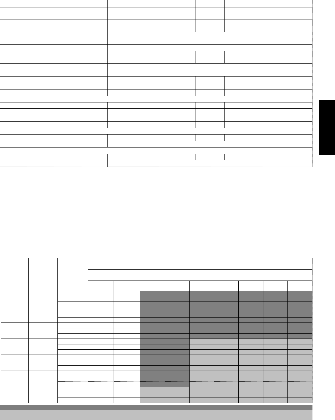
VAPOR LI NE SIZING AND COOLING CAPACITY LOSS
LONG LINE APPLICATION: An ap plication is con sidered ”Long
line” when the total equivalent tubing length e xceeds 80 ft. (24.38
m) or when there is more than 20 ft. (6.09 m) vertical separation
between indoor and outdoor units. These applications require
additional accessories and system modifications for r eliable system
operation. The maximum allowable total equivalent length is up to
250 ft. (76.2 m). The maximum vertical separation 200 ft. (60.96
m) when outdoor unit is above indoor unit, and up to 80 ft. (24.38
m) when the outdoor unit is below the indoor unit. Refer to
Accessory Usage Guideline below for required accessories. See
Longline Application Guideline for required piping and system
modifications. Also, refer to the table below for the vapor tube
diameters based on the total length to minimize the cooling
capacity loss.
Unit
Nominal
Size (Btuh)
Maximum
Liquid Line
Diameters
(In. OD)
Vapor Line
Diameters
(In. OD)
Cooling Capacity Loss (%)
Total Equivalent Line Le ngth ft. (m)
Standard
Application
Long Line Application Requires Accessories
26---50
(7.9---15.2)
51---80
(15.5---24.4)
81---100
(24.7---30.5)
101---125
(30.8---38.1)
126---150
(38.4---45.7)
151---175
(46.0---53.3)
176---200
(53.6---61.0)
201---225
(61.3---68.6)
226---250
(68.9---76.2)
18000
1Stage
Puron AC
3/8
1/2 1 2 3 5 6 7 8 9 11
5/8 0 1 1 1 2 2 2 3 3
3/4 0 0 0 0 1 1 1 1 1
24000
1Stage
Puron AC
3/8
5/8 0 1 2 2 3 3 4 5 5
3/4 0 0 1 1 1 1 1 2 2
7/8 0 0 0 0 0 1 1 1 1
30000
1Stage
Puron AC
3/8
5/8 1 2 3 3 4 5 6 7 8
3/4 0 0 1 1 1 2 2 2 3
7/8 0 0 0 0 1 1 1 1 1
36000
1Stage
Puron AC
3/8
5/8 1 2 4 5 6 8 9 10 12
3/4 0 1 1 2 2 3 3 4 4
7/8 0 0 0 1 1 1 1 2 2
42000
1Stage
Puron AC
3/8
3/4 0 1 2 2 3 4 4 5 6
7/8 0 0 1 1 1 2 2 2 3
11/8 0 0 0 0 0 0 0 0 0
48000
1Stage
Puron AC
3/8
3/4 0 1 2 3 4 5 5 6 7
7/8 0 0 1 1 2 2 2 3 3
11/8 0 0 0 0 0 0 0 1 1
60000
1Stage
Puron AC
3/8
3/4 1 2 4 5 6 7 9 10 11
7/8 0 1 2 2 3 4 4 5 5
11/8 0 0 0 1 1 1 1 1 1
Applications in thisarea are long line. Accessoriesare required asshown recommended on Long Line Application Guidelines
Applications in this area may have height restrictions that limit allowable total equivalentlength, when outdoor unit is below indoor unit See Long Line Applica-
tion Guidelines
113A