


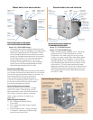
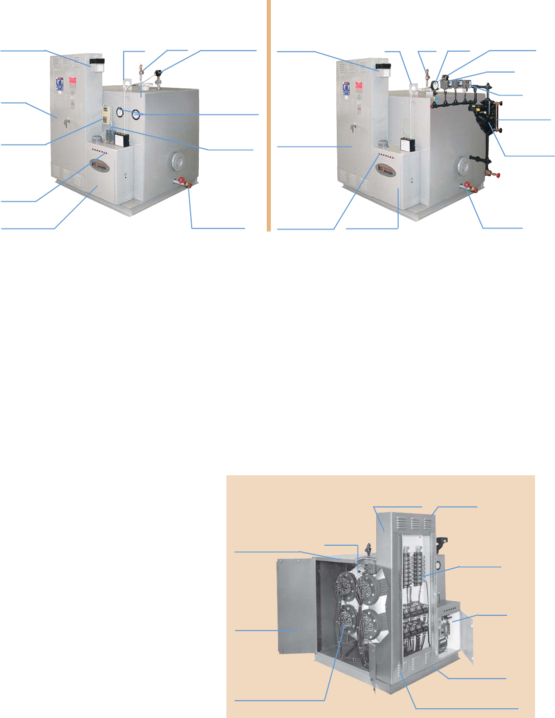
Water boiler trim and controls
Steam boiler trim and controls
Step
indicating
lights
Control panel
Lifting
lugs
ASME
relief
valve
Pressure and
temperature
gauges
(2) High
limit controls
Drain
Operating
control
Probe type low
water cutoff
control
Power
panel
Fused control
circuit
transformer
Blowdown
Fused
control circuit
transformer
Step
Indicating lights Control panel
Power
panel
Lifting
lugs
Standard Equipment Supplied:
HOT WATER DESIGN BOILERS:
Model “W” (150# ASME Design)
Temperature and pressure gauge, Operating immer-
sion aquastat, 2 high limit aquastats, Low water cutoff,
Relief valve, Metal jacket with 4؆ fiberglass, 75 W/D
Incoloy sheathed elements with pressure connector
power lugs. Separate power panel and control panel,
On/Off control switch, 120 volt control transformer
(fused), Magnetic contactors with 120 volt coil,
Individual circuit Class JKS fusing, Step indicating
lamps, First on/first off progressive step controller,
National Board Inspection and UL Label.
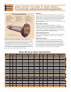
Power Circuit Design:
All Bryan BH Series boilers feature copper bus bar distribu-
tion, wherein the fuse clip for each branch circuit and the
main power lugs are all bolted directly to a bus bar. The
bus bar can carry the full load current of the
boiler, withstanding the largest available fault
current from the entering power system. Use of
the bus bar protects all current-carrying parts
and prevents damage to the boiler.
Optional Equipment Available:
Power panel door electric interlock. Preheat
switch. Flow switch. Manual reset controls.
Manual blowdown valve. Automatic blowdown
with 24 hour time clock. Alarms. Indicating
lights. Larger connection for heat pump
applications.
Other Designs Available:
1) BE – Economical Electric Boilers
(Form 3600)
2) WT – Indirect Hot Water Supply Heaters
(Form 4800)
3) Energy Selector Boiler – Electric plus gas,
oil or gas/oil. A boiler with multiple energy
source choice (Form 3500)
Standard Equipment Supplied:
STEAM DESIGN BOILERS:
Model “S” (15# ASME Design)
Model “Q” (150# ASME Design)
Steam pressure gauge w/gauge clock, Operating
pressure control, 2 high limit pressure controls,
Combination low water cutoff and pump control,
Auxiliary low water cutoff, Relief valve, Water glass
set, Metal jacket with 4؆ fiberglass, 75 W/D Incoloy
sheathed elements with pressure connector power
lugs. Separate power panel and control panel, On/off
control switch, 120 volt control transformer (fused),
Magnetic contactors with 120 volt coil, Individual circuit
Class JKS fusing, Step indicating lamps, First on/ first
off progressive step controller, National Board Inspec-
tion and UL Label.
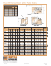
Standard Design Features
ASME
relief
valve
Pressure
gauge
Probe type
low water
cutoff control
(2) high limit
controls
Operating
control
Water level
gauge glass
Low water
cutoff and
pump control
Heavy duty 11
gauge power
panel cabinet
Single point
electric
connection
Each branch
circuit is fused
indivdually using
copper bus bar
for power
distribution
Separate
control panel
for 120V
controls
4" channel base
Louvered panel cover for
proper cooling air circulation
Immersion heating
bundles broken down in
150 KW bundles or less
16 gauge jacketing all
around structural frame
(zinc-coated rust
resistant primer and
enamel finished).
Hinged
access
door for
access to
vessel,
ASME and
elements
4" fiberglass
insulation