


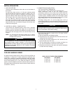
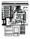
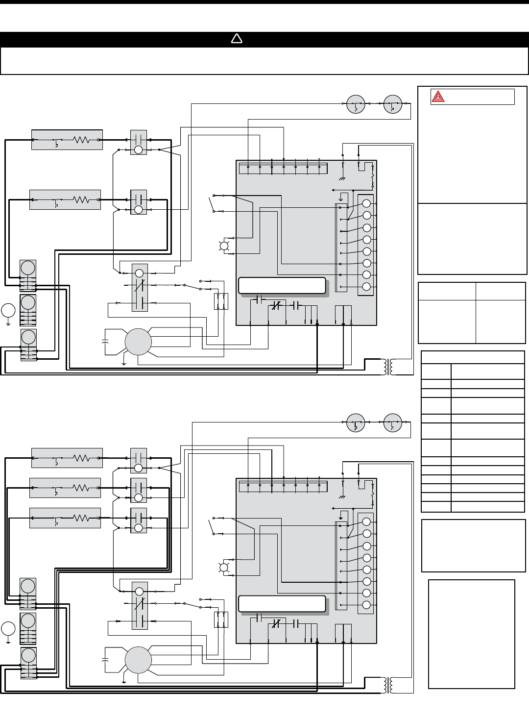
WIRING DIAGRAMS
WARNING
Risk of electrical shock. Disconnect power before installation, servicing, maintenance or field wiring. Replace all panels before
operating. Failure to do so can result in electrical shock causing severe injuries or death.
!
7
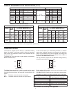
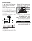
Line voltage wiring:
UL AWM 1015/1230, 600V, 105°C,
VW-1,12AWG;
CSA TEW 600V, 105°C,
FT1, 12AWG.
Low voltage wiring: same ratings
as high voltage except 18AWG.
Critical Characteristic
1. If any of the original wire, as
supplied, must be replaced,
use the same equivalent wire.
Wiring must comply with
applicable codes, ordinances
and regulations.
2. Field wiring must comply with
applicable codes, ordinances
and regulations. Use only
Class 1 wiring inside furnace
compartments.
For the use of a two-stage heat
thermostat or an outdoor
thermostat, connect between
W1 and W2. Make sure that the
Season Select switch
is set to the Mild Position.
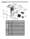
HI BLACK
MED-HIGH BLUE
MED-LOW YELLOW
LOW RED
FAN
MOTOR SPEED
COLOR
WIRING COLOR CODE
BLK BLACK
BLU BLUE
BRN BROWN
GRN GREEN
GRY GREY
ORG ORANGE
PNK PINK
PPL PURPLE
RED RED
WHT WHITE
YEL YELLOW
LEGEND
C Capacitor
F1 Fuse
E Heating Element
KC Heating Element
Relay
K Fan Relay
HTL Auto-Reset
Thermal Protector
MRHTL Manual Reset
Thermal Protector
M Fan Motor
TB Terminal Block
T Transformer Class 2
HEAT Heat
L1, L2 240V Line Supply
N Neutral
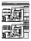
24 VAC
24 VAC
COMMON OUT
FUSED 24 VAC
POWER OUT
CALL FOR FAN.
CALL FOR COOL.
CALL FOR HEAT 2
CALL FOR COOL 1
BOARD POWER
SUPPLY
POWER
HEAT 1
HEAT 2
HEAT 3
HEAT 4
VOUT
GND
YELYEL
BLK
PPL
P2
P1
GRY
PPL
PPL
PPL
BLK
HEAT
COOL
FAN
XFMR
VSPOWER
L1
L2COM
L2
L2COM2
BLK RED
ORG
ORG BLK
P2-8
P2-4
P2-3
P2-2
P2-1
P2-5
P2-6
P2-7
10 kW 240 VAC
Single phase
Y1
W2
W1O
Y/Y2
G
R
C
F1
5 AMPS
P3
P3-1 P3-2 P3-3
P3-4 P3-5
P3-6
P3-7
WHT
GRY
K1K2
K2
HEAT INDICATOR
GRY
REVERSING VALVE
CALL FOR HEAT 1
G
L1
Class 2 Transformer
Pri: 240 V 60 Hz
Sec: 24 V 60 Hz 40 VA
YEL
YEL
RED
BLK
BLK
BLK
HEAT 3
HEAT 1
PNK
GRY
WHT
VENTILATION SPEED
WHT
PNK
T
BLK
BLK
WHT
Open: 93.3°C (200°F)
MRHTL1
WHTWHT
BLK (HI)
BLU (MED-HI)
RED (LO)
YEL (MED-LO)
MRHTL2
N
PNK
KC1
24VDC
COM
NO
KC3
24VDC
COM
NO
L2
RED
RED
RED
HEAT 1
E
HTL
KLBDER
HEAT 3
E
HTL
KLBDER
K7
24VDC
4
6
2
5
13
PNK
YEL
BLU
ORG
NC
HI
Med-Hi
Med-Lo
Lo
M
TB
RED
YEL
MED-LO
LO
BLK
C
BLK
ORG
RED
BRN
BRN
BLU RED
SEASON SELECT
WHT
WHT
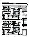
24 VAC
24 VAC
COMMON OUT
FUSED 24 VAC
POWER OUT
CALL FOR FAN.
CALL FOR COOL.
CALL FOR HEAT 2
CALL FOR COOL 1
BOARD POWER
SUPPLY
POWER
HEAT 1
HEAT 2
HEAT 3
HEAT 4
VOUT
GND
YEL
YEL
BLK
PPL
P2
P1
GRY
PPL
PPL
PPL
BLK
HEAT
COOL
FAN
XFMR
VSPOWER
L1
L2COM
L2
L2COM2
BLK RED
ORG
ORG BLK
P2-8
P2-4
P2-3
P2-2
P2-1
P2-5
P2-6
P2-7
15 kW 240 VAC
Single phase
Y1
W2
W1OY/Y2
GR
C
F1
5 AMPS
P3
P3-1 P3-2 P3-3
P3-4 P3-5
P3-6
P3-7
WHT
GRY
K1K2
K2
HEAT INDICATOR
SEASON SELECT
GRY
REVERSING VALVE
CALL FOR HEAT 1
G
L1
Class 2 Transformer
Pri: 240 V 60 Hz
Sec: 24 V 60 Hz 40 VA
YEL
YEL
RED
BLK
BLK
BLK
BLK
HEAT 3
HEAT 2
HEAT 1
PNK
BRN
GRY
WHT
WHT
VENTILATION SPEED
WHT
PNK
T
BLK
BLK
BLK
WHT
Open: 93.3°C (200°F)
MRHTL1
WHTWHT
BLK (HI)
BLU (MED-HI)
RED (LO)
YEL (MED-LO)
MRHTL2
N
BRN
PNK
KC1
24VDC
COM
NO
KC2
24VDC
COM
NO
KC3
24VDC
COM
NO
L2
REDRED
RED
RED
HEAT 1
E
HTL
KLBDER
HEAT 2
E
HTL
RED
BLK
HEAT 3
E
HTL
KLBDER
K7
24VDC
4
6
2
5
13
PNK
BLU
BLU
ORG
NC
HI
Med-Hi
Med-Lo
Lo
M
TB
RED
YEL
MED-LO
LO
BLK
C
BLK
ORG
RED
BRN
BRN
YEL
RED
WHT
WHT