


3
Special Requirements For Interconnected Smoke Alarms
• Failure to meet any of the above requirements could damage the units and cause them to
malfunction, removing your protection.
• AC and AC/DC Smoke Alarms can be interconnected. Under AC power, all units will alarm when
one senses smoke. When power is interrupted, only the AC/DC units in the series will continue to
send and receive signals. AC powered Smoke Alarms will not operate.
Interconnected units can provide earlier warning of fire than stand-alone units, especially if a fire starts in a remote
area of the dwelling. If any unit in the series senses smoke, all units will alarm. To determine which Smoke Alarm
initiated an alarm, see table:
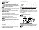
On Initiating Alarms Red LED(s) flashes(flash) rapidly
On All Other Alarms Red LED is Off
Interconnect units within a single family residence only. Otherwise all households will experience unwanted
alarms when you test any unit in the series. Interconnected units will only work if they are wired to compatible
units and
all requirements are met. This unit is designed to be compatible with:
First Alert
®
Smoke Alarm Models SA4120, SA4121B, SA4919B, SA100B and BRK Electronics
®
Smoke Alarm
Models 100S, 2002RAC, 4120, 4120B, 4120SB, 4919, 5919, 5919TH; BRK Electronics
®
Heat Alarm Models
HD6135F, HD6135FB; Smoke/CO Alarm Model SC6120B; Relay Module RM3.
Interconnected units must meet ALL of the following requirements:
• A maximum of 18 compatible units may be interconnected (Maximum of 12 Smoke Alarms).
• The same fuse or circuit breaker must power all interconnected units.
• The total length of wire interconnecting the units should be less than 1000 feet (300 meters). The intercon-
nect wire should be #18 gauge or larger, rated at least 300V. If an interconnect wire is not already part of
your household wiring, you will need to install one. This type of wire is commonly available at Hardware
and Electrical Supply stores.
•
All wiring must conform to all local electrical codes and Article 760 of NFPA 70 (NEC). Refer to NFPA 72, NFPA
101, and/or your local building code for further connection requirements.
6
7
8
4
3
1
5
4
3
1
5
2
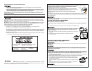
A
B
}
}
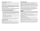
A. Unswitched 120VAC
60 Hz source
B. To additional units; Maximum = 18 total
(Maximum 12 Smoke Alarms)
1. Smoke Alarm
2. Ceiling or Wall
3. Power Connector
4. Wire Nut
5. Junction Box
6. Neutral Wire (Wht)
7. Interconnect Wire
(Orange)
8. Hot Wire (Blk)
LOCKING FEATURES
The locking features are designed to prevent unauthorized removal of the battery or Alarm. It is not
necessary to activate the locks in single-family households where unautho-
rized battery or Alarm removal is not a concern.
These Smoke Alarms have two separate locking features: one to lock the battery
compartment, and the other to lock the Smoke Alarm to the mounting bracket. You
can choose to use either feature independently, or use them both.
Tools you will need: • Needle-nose pliers or utility knife • Standard/Flathead
screwdriver.
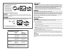
Both locking features use locking pins, which are molded into the mounting bracket. Using needle nose pliers
or a utility knife, remove one or both pins from the mounting bracket, depending on how many locking fea-
tures you want to use.
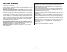
To permanently remove either lock, insert a flathead screwdriver between the locking pin and the lock,
and pry the pin out of the lock.
Locking Pin
TO LOCK THE BATTERY COMPARTMENT
(Models SA4121B, 4120B, and 4120SB Only)
Do not lock the battery compartment until you have installed the battery and tested the battery back-
up.
1. Push and hold test button until the alarm sounds: 3 beeps, pause, 3 beeps, pause.
If the unit does not alarm during testing, DO NOT lock the battery compartment!
Install a new battery and test again. If the Smoke Alarm still does not alarm,
replace it immediately.
2. Using needle-nose pliers or a utility knife, detach one locking pin from the mount-
ing bracket.
3. Push the locking pin through the black dot on the label on the back
of the Smoke Alarm.
TO UNLOCK THE BATTERY COMPARTMENT
(Models SA4121B, 4120B, and 4120SB Only)
Once the Smoke Alarm is installed, you must disconnect it from the AC power before unlocking the battery
compartment.
ELECTRICAL SHOCK HAZARD. Turn off the power to the area where the Smoke Alarm is installed
before removing it from the mounting bracket. Failure to turn off the power first may result in serious
electrical shock, injury or death.
Always discharge the branch circuit before servicing an AC or AC/DC Smoke Alarm. First, turn off the AC
power at the circuit breaker or fuse box. Next, remove the battery from Smoke Alarms with battery back-
up. Finally, press and hold the test button for 5-10 seconds to discharge the branch circuit.
1. Remove the Smoke Alarm from the mounting bracket. If the unit is locked to the bracket, see the section
“To Unlock the Mounting Bracket.”
2. Disconnect the power connector by gently prying it away from the back of the Smoke Alarm.
3. Insert a flathead screwdriver under the head of the locking pin, and gently pry it
out of the battery compartment lock. (If you plan to relock the battery compart-
ment, save the locking pin.)
4. To relock the battery compartment, close the battery door and reinsert locking pin
in lock.
5. Reconnect the power connector to the back of the Smoke Alarm, reattach the
Smoke Alarm to the mounting bracket, and restore the power.
When replacing the battery, always test the Smoke Alarm before relocking the battery compartment.
Models SA4121B and 4120SB Only: During installation, if you accidentally press the Silence button, the alarm
will “chirp” once a minute for up to 15 minutes and the Test feature will be temporarily disabled. This is normal.
The “chirping” will stop once the alarm returns to normal operation.