


HOW TO INSTALL THIS SMOKE ALARM
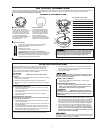
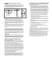
THE PARTS OF THIS SMOKE ALARM
P
arts of the Smoke Alarm
1
Mounting slot and screw (1 of 2)
2 Junction box
3
Mounting bracket
4
Mounting Bracket Alignment Arrow
5 Mounting slot and screw (1 of 2)
6
Wire strip gauge
7
Neutral (white) AC wire
8 Hot (black) AC wire
9
Interconnect wire
10 Foam gasket
11 Alignment Tab On Alarm
1
2 Turn to attach to bracket
13 Turn to remove from bracket
The Mounting Bracket
Installs onto the junction box.
I
t has a variety of screw slots to fit
most boxes. If a junction box is
not already in place, install one.
T
o remove the mounting bracket
from the Smoke Alarm base,
hold the Smoke Alarm base firmly
a
nd twist mounting bracket
counterclockwise.
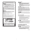
The Power Connector
The power connector plugs into a power input block
on the Smoke Alarm and supplies it AC power.
•Black wire is “hot.”
•White wire is neutral.
•
Orange wire is used for interconnect.
I
f you need to remove the power connector, turn
POWER OFF first. To
remove the power connector,
insert
a
flat screwdriver blade between the power connector and
t
he security tab inside the power input block. Gently pry
back the tab and pull the connector fre
e.
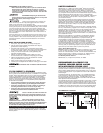
T
he Foam Gasket
The foam gasket prevents air
c
urrents from coming through
t
he junction box and blowing
smoke away from the sensor.
I
t must be installed to comply
w
ith UL standards. When
installing the foam gasket, line
u
p the cut-outs with the power
i
nput block on the Smoke Alarm.
T
his Smoke Alarm is designed to be mounted on any standard wiring junction box to a 4-inch (10 cm) diagonal size, on ether the ceiling or wall (if allowed
b
y local codes). Read “Recommended Locations For Smoke Alarms” and “Locations to Avoid For Smoke Alarms” before you begin installation.
Tools you will need: Standard Flathead screwdriver.
M
ake sure the Alarm is not receiving excessively
noisy power. Examples of noisy power could be major appliances
on the same circ
uit, power from a generator or solar power,
light
d
immer on the same circuit or mounted near fluorescent lighting.
Excessively noisy power may cause damage to your Alarm
.
2
FOLLOW THESE INSTALLATION STEPS
The basic installation of this Smoke Alarm is the similar whether you
want to install one Smoke Alarm, or interconnect more than one
Smoke Alarm. If you are interconnecting more than one Smoke
Alarm, you MUST read “Special Requirements For Interconnected
Smoke Alarms” below before you begin installation.
ELECTRICAL SHOCK HAZARD! Turn off power before starting
installation!
1. Remove the mounting bracket from the base. Install the mounting
bracket to the junction box
2. Set the foam gasket against the back of the Smoke Alarm.
3. Using wire nuts, connect the power connector to the household
wiring.
STAND-ALONE ALARM ONLY:
• Connect the white wire on the power connector to the neutral
wire in the junction box.
•
Connect the black wire on the power connector to the hot wire
in the junction box.
•
Tuck the orange wire inside the junction box. It is used for
interconnect only.
INTERCONNECTED UNITS ONL
Y
:
Strip off about 1/2” (12 mm) of the plastic coating on the orange
wir
e on the power connector.
•
Connect the white wire on the power connector to the neutral
wire in the junction box.
• Connect the black wire on the power connector to the hot wire
in the junction box.
•
Connect the orange wire on the power connector to the inter-
connect wir
e in the junction box. Repeat for each unit you ar
e
interconnecting. Never connect the hot or neutral wires in the
junction box to the orange interconnect wire.
5. Line up the alignment tab on the base with the alignment tab on
the mounting bracket. Turn the Smoke Alarm clockwise (right)
until you hear the unit snap into place.
6. Check all connections.
Improper wiring of the power connector or the wiring leading to
the power connector will cause damage to the Alarm and may
lead to a non-functioning Alarm.
7.
Make sur
e the Smoke Alarm is r
eceiving AC power
. Under normal
operation, the green power indicator light will shine continuously.
If the power indicator light does not light, TURN OFF POWER TO
THE JUNCTION BOX and recheck all connections. If all connec-
tions ar
e corr
ect and the power indicator still does not light when
you restore the power, the unit should be replaced immediately.
8. Test the Smoke Alarm. Press and hold the test button on the
cover of the unit until the alarm sounds (the unit may continue to
alarm for a few seconds after you release the button).
During
testing, you will hear a loud, repeating horn pattern: 3 beeps,
pause, 3 beeps, pause. In an inter
connected series, you must
test each Smoke Alarm individually.
4. Plug the power connector into the back of the Smoke Alarm.
STAND-ALONE ALARM ONLY:
• If you ar
e only installing one Smoke Alarm, r
estore power
to the junction box.
INTERCONNECTED UNITS ONL
Y
:
•
If you are inter
connecting multiple Smoke Alar
ms, repeat
steps 1-6 for each Smoke Alarm in the series. When you
are finished, restore power to the junction box.
ELECTRICAL SHOCK HAZARD! Do not restore power until all
smoke alar
ms are completely installed. Restoring power before
installation is complete may result in serious electrical shock,
injury or death.
If any Smoke Alarm does not alarm, TURN OFF POWER and recheck
connections. If any Smoke Alarm still does not alarm when you test it
after r
estoring power
, r
eplace it immediately.