


BEFORE YOU BEGIN INSTALLATION
This unit is designed to be mounted on any standard wiring junction box up
to a 4-inch (10 cm) size, on either the ceiling or wall. Read “Wher
e to Install CO
Alarms” and “Wher
e Not To Install CO Alarms” before you begin installation.
• This Alarm must have AC or battery power to operate. If the AC
power fails, the batter
y back-up will power the Alarm for a short
time if the 9V batter
y is fresh and correctly installed. If AC power
fails, and the battery is dead or missing, the Alarm cannot operate.
•
Make sure the alarm is not receiving excessive noisy power.
Examples of noisy power could be major appliances on the same
circuit, power from a generator or solar power, light dimmer on the
same cir
cuit or mounted near fluorescent lighting. Excessive noisy
power may cause damage to your Alar
m.
Find the pair of self-adhesive labels included with this CO Alarm.
•
On each label write in the phone number of your emergency responder
(like 911) and a qualified appliance technician.
•
Place one label near the CO Alarm, and the other label in the “fresh air”
location you plan to go if the alarm sounds.
NOTE: A qualified appliance technician is defined as “a person, firm, corporation,
or company that either in person or through a representative, is engaged in and
r
esponsible for the installation, testing, servicing, or replacement of heating,
ventilation, air conditioning (HV
AC) equipment, combustion appliances and
equipment, and/or gas fireplaces or other decorative combustion equipment.”
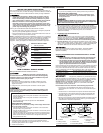
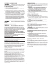
PARTS OF THIS CO ALARM
1 Mounting Bracket
2 Mounting Slot and Screw*
3 Locking Pins (break out of
bracket)
4 Hot (Black) AC Wire
5 Neutral (White) AC Wire
6
Interconnect Wire (Orange)
7 Lever to Open Battery
Compartment
8 Swing-Out Battery
Compartment
9 Quick-Connect Power
*Not Included
1
2
3
2
9
8
7
3
5
6
4
Tools you will need: Standard Flathead screwdriver.
ELECTRICAL SHOCK HAZARD. Turn off power to the area where you
will install this unit at the circuit breaker or fuse box before beginning
installation. Failure to turn off the power before installation may result
in serious electrical shock, injury or death.
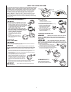
To install this unit:
1. Remove the mounting bracket from the base. Position the screw
slots on the mounting bracket over the screws in the junction box.
Tighten the scr
ews.
2. Using wire nuts, connect the power connector to the AC power.
Impr
oper wiring of the power connector or the wiring leading to the
power connector will cause damage to the Alarm and may lead to a
non-functioning Alarm.
3. Plug the power connector into the back of the CO Alarm.
4. Position the base of the Alarm over the mounting bracket and turn.
The Alarm can be positioned over the bracket every 60°. Turn the unit
clockwise (right) until the unit is in place.
5. Check all connections.
STAND ALONE ALARM ONLY:
• Connect the white wire on the power connector to the neutral wire
in the junction box.
• Connect the black wire on the power connector to the hot wire in
the junction box.
• Tuck the orange wire inside the junction box.
It is used for
interconnect only.
INTERCONNECTED ALARMS ONLY:
Strip off about 1/2” of the plastic coating on the orange interconnect
wire on the power connector.
•
Connect the white wir
e on the power connector to the neutral wir
e
(usually white) in the junction box.
• Connect the black wire on the power connector to the hot wire (usual-
ly black) in the junction box.
• Connect the orange wire on the power connector to the interconnect
wire in the junction box. Repeat for each unit you are interconnecting.
Never connect the hot or neutral wir
es in the junction box to the
orange inter
connect wir
e.
SPECIAL REQUIREMENTS FOR INTERCONNECTED CO ALARMS
• Failure to meet any of the above requirements could damage the
units and cause them to malfunction, removing your protection.
• AC and AC/DC CO Alarms can be interconnected. Under AC power,
all units will alarm when one senses CO. When power is interrupted,
only the AC/DC units in the series will continue to send and receive
signals. AC powered CO Alarms will not operate.
Interconnected units can provide earlier warning of a CO problem than stand-
alone units, especially if the problem starts in a remote area of the dwelling.
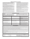
If any unit in the series senses CO, all CO and Smart Interconnect units will
alarm. To determine which CO Alarm initiated an alarm, refer to the table.
On Initiating CO Alarm Red LED Flashes the alarm pattern
On All Other CO Alarms Red LED Does Not Flash the alarm pattern
Interconnect units within a single family residence only. Otherwise all house-
holds will experience unwanted alarms when you test any unit in the series.
Interconnected units will only work if they are wired to compatible units and
all requirements are met.
This unit is designed to be compatible with:
BRK Electronics
®
and First Alert
®
Models 7010, 7010B, 7020B, SC7010B,
SA520B, 9120, 9120B, SC9120B, 100S, SL177,
SC7010BV,
CO5120BN,
CO5120PDBN, HD6135F
, HD6135FB.
Interconnected units must meet ALL of the following requirements:
• A maximum of 18 compatible Smoke, Heat or CO Alarms may be
interconnected. No more than 12 of the 18 can be Smoke Alarms per
NFPA 72.
• The same fuse or circuit breaker must power all interconnected units.
•
The total length of wir
e inter
connecting the units should be less than
1000 feet. This type of wire is commonly available at Hardware and
Electrical Supply stores.
• All wiring must conform to all local electrical codes and Articles 210 and
300.3 (B) of the National Electrical Code. Refer to your local building
code for further connection r
equir
ements.
6.
Make sure the CO Alarm is receiving AC power. Under normal operation,
the r
ed indicator light will shine continuously.
If the r
ed power indicator light
does not light, TURN OFF POWER TO THE JUNCTION BOX and r
echeck
all connections. If all connections are correct and the red power indicator
still does not light when you r
estore the power, the unit should be
r
eplaced immediately.
7.
ACTIV
ATING THE BATTERY BACK-UP
Activate the battery back-up by r
emoving the “Pull to Activate Battery
Back-Up” tab. You do not need to open the battery compartment and
r
eposition the battery during installation.
DO NOT r
emove the battery
activation tab until AC power is tur
ned on to conserve battery power.
8. T
est the CO Alarm.
Pr
ess and hold the test button on the cover until the
alarm sounds: 4 beeps, pause, 4 beeps, pause. In a series of interconnected
Alarms, you must test each Alarm separately by pr
essing and holding the
test button. Make sur
e all units alarm when each one is tested.
If any unit in the series does not alarm during testing, TURN OFF POWER
and recheck connections. If it does not alarm when you restore power,
replace it immediately.
6
7
8
4
3
1
5
4
3
1
5
2
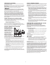
A
B
}
}
A. Unswitched 120VAC B. To Additional Alarms,
60 Hz source Maximum = 18 Alarms
1. CO Alarm
2. Ceiling or W
all
3. Power Connector
4. Wire Nut
5. Junction Box
6. Neutral Wire (White)
7. Interconnect Wire
(Orange)
8. Hot Wire (Black)
ST
AND ALONE ALARM ONLY:
•
If you are only installing one unit, restore power to the junction box.
INTERCONNECTED ALARMS ONL
Y:
•
If you are interconnecting multiple Alarms, repeat Step 1-5 for
each Alarm in the series. When you are finished, restore power
to the junction box.
ELECTRICAL SHOCK HAZARD. Do not restore power until all Alarms are
completely installed. Restoring power befor
e installation is complete may
result in serious electrical shock, injury or death.
HOW TO INSTALL YOUR CO ALARM
INST
ALLATION, continued
3