


2
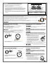
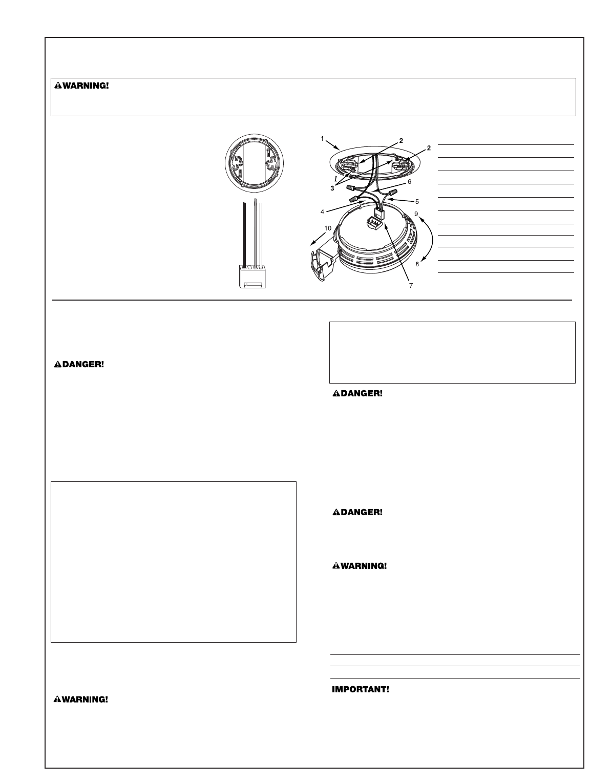
The Mounting Bracket:
To remove the mounting bracket from the Smoke
Alarm base, hold the Smoke Alarm base firmly and
twist the mounting bracket counterclockwise. The
mounting bracket installs onto the junction box. It
has a variety of screw slots to fit most boxes.
The Power Connector:
The power connector plugs into a power input block on
the Smoke Alarm. It supplies the unit with AC power.
• The black wire is “hot.”
• The white wire is neutral.
• The orange wire is used for interconnect.
If you need to remove the power connector, turn
POWER OFF first. Insert a flat screwdriver blade
between the power connector and the security tab
inside the power input block. Gently pry back the tab
and pull the connector free.
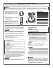
The Parts of This Unit
1 Mounting Bracket
2 Mounting Slots
3 Locking Pins (break out of bracket)
4 Hot (Black) AC Wire
5 Neutral (White) AC Wire
6 Interconnect (Orange) Wire
7 Quick-Connect Power Connector
8 Turn this way to remove from bracket
9 Turn this way to attach to bracket
10 Slide-Out Battery Drawer
HOW TO INSTALL THIS SMOKE ALARM
This Smoke Alarm is designed to be mounted on any standard wiring junction box up to a 4-inch size, on either the ceiling or wall (if allowed by local codes).
Read “Recommended Locations For Smoke Alarms” and “Locations to Avoid For Smoke Alarms” before you begin installation.
Tools you will need: • Needle-nose pliers or utility knife • Standard Flathead screwdriver.
FOLLOW THESE INSTALLATION STEPS
Make sure the Alarm is not receiving excessively noisy power. Examples of noisy power could be major appliances on the same circuit, power from a
generator or solar power, light dimmer on the same circuit or mounted near fluorescent lighting. Excessively noisy power may cause damage to your
Alarm.
THE PARTS OF THIS SMOKE ALARM
The basic installation of this Smoke Alarm is similar whether you want to
install one Smoke Alarm, or interconnect more than one Smoke Alarm. If
you are interconnecting more than one Smoke Alarm, you MUST read
“Special Requirements For Interconnected Smoke Alarms” below before
you begin installation.
ELECTRICAL SHOCK HAZARD. Turn off power to the area where you will
install this unit at the circuit breaker or fuse box before beginning instal-
lation. Failure to turn off the power before installation may result in seri-
ous electrical shock, injury or death.
1. Remove the mounting bracket from the base, and attach it to the
junction box.
Model 7010B Only: Activate the battery back-up by removing the “Pull
to Activate Battery Back-Up” tab. Or, install battery back-up. Battery
back-up cannot work until you install the battery in the correct position
(Match “+” to “+” and “-” to “-”).
Push and hold test button until the alarm sounds:
3 beeps, pause, 3 beeps, pause.
2. Using wire nuts, connect the power connector to the household wiring.
3. Plug the power connector into the back of the Smoke Alarm.
4.
Position the base of the Smoke Alarm over the mounting bracket and
turn. The Alarm can be positioned over the bracket every 90°. Turn the
Smoke Alarm clockwise (right) until the unit is in place.
5. Check all connections.
Improper wiring of the power connector or the wiring leading to the
power connector will cause damage to the Alarm and may lead to a
non-functioning Alarm.
STAND-ALONE ALARM ONLY:
• Connect the white wire on the power connector to the neutral wire in
the junction box.
• Connect the black wire on the power connector to the hot wire in the
junction box.
• Tuck the orange wire inside the junction box. It is used for
interconnect only.
INTERCONNECTED UNITS ONLY:
Strip off about 1/2” (12 mm) of the plastic coating on the orange wire
on the power connector.
• Connect the white wire on the power connector to the neutral wire in
the junction box.
• Connect the black wire on the power connector to the hot wire in the
junction box.
•
Connect the orange wire on the power connector to the interconnect
wire in the junction box. Repeat for each unit you are interconnecting.
Never connect the hot or neutral wires in the junction box to the orange
interconnect wire. Never cross hot and neutral wires between Alarms.
ELECTRICAL SHOCK HAZARD. Do not restore power until all Smoke
Alarms are completely installed. Restoring power before installation is
complete may result in serious electrical shock, injury or death.
6. Make sure the Smoke Alarm is receiving AC power. Under normal oper-
ation, the Green power indicator light will shine continuously.
7. If the Green power indicator light does not light,
TURN OFF POWER
TO THE JUNCTION BOX and recheck all connections. If all connec-
tions are correct and the Green power indicator still does not light when
you restore the power, the unit should be replaced immediately.
8. Test each Smoke Alarm. Press and hold the Test/Silence button until the
unit alarms.
When testing a series of interconnected units you must
test each unit individually. Make sure all units alarm when each one
is tested.
If any unit in the series does not alarm, TURN OFF POWER and
recheck connections. If it does not alarm when you restore power, replace it
immediately.
STAND-ALONE ALARM ONLY:
• If you are only installing one Smoke Alarm, restore power to the
junction box.
INTERCONNECTED UNITS ONLY:
• If you are interconnecting multiple Smoke Alarms, repeat steps
1-5 for each Smoke Alarm in the series. When you are finished,
restore power to the junction box.
Special Requirements For Interconnected Smoke Alarms
• Failure to meet any of the above requirements could damage the
units and cause them to malfunction, removing your protection.
• AC and AC/DC Smoke Alarms can be interconnected. Under AC
power, all units will alarm when one senses smoke. When power is
interrupted, only the AC/DC units in the series will continue to send
and receive signals. AC powered Smoke Alarms will not operate.
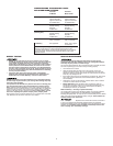
Interconnected units can provide earlier warning of fire than stand-alone units,
especially if a fire starts in a remote area of the dwelling. If any unit in the series
senses smoke, all units will alarm. To determine which Smoke Alarm initiated an
alarm, see table:
On Initiating Alarms Red LED flashes rapidly
On All Other Alarms Red LED is Off
Interconnect units within a single family residence only. Otherwise all house-
holds will experience unwanted alarms when you test any unit in the series.
Interconnected units will only work if they are wired to compatible units and
all requirements are met. This unit is designed to be compatible with:
First Alert
®
Smoke Alarm Models SA4120, SA4121B, SA100B and BRK
Electronics
®
Smoke Alarm Models 100S, 2002RAC, 4120, 4120B, 4120SB,
5919; BRK Electronics
®
Heat Alarm Models HD6135F, HD6135FB;
Smoke/CO Alarm Model SC6120B; Relay Module RM3.
Continued...