10 BRIGGSandSTRATTON.COM
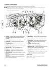
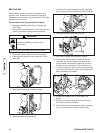
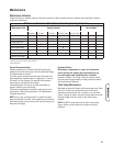
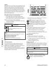
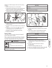
A - Data Tag — Provides model and serial number of trash
pump. Please have these readily available if calling for
assistance.
B - Pump Faceplate — Remove to clean impeller.
C - Suction Inlet — Connect reinforced suction hose here.
D - Priming Plug — Fill pump with water here to prime
pump before starting.
E - Fuel Tank — Fill tank with regular unleaded fuel. Always
leave room for fuel expansion.
F - Discharge Outlet — Connect discharge hose here.
G - Choke Lever — Prepares a cold engine for starting.
H - Air Cleaner — Protects engine by filtering dust and
debris out of intake air.
J - Fuel Shutoff Valve — Used to turn fuel supply on and off
to engine.
Model 073017 — located behind the air cleaner on the
carburetor.
Model 073018 — located to the left of the engine speed
lever on the engine control panel.
K - Recoil Starter — Used for starting the engine manually.
L - Engine Speed Lever — Used to adjust engine speed to
control pump output.
M - On/Off Switch — Set this switch to “On” before using
recoil starter. Set switch to “Off” to stop a running
engine.
N - Oil Drain — Drain engine oil here.
P - Oil Fill — Check and add engine oil here.
Q - Water Drain Plugs — Remove to drain water from pump
and flush internal components with clean water.
S - Pump Chamber — Be sure to fill with water before
starting.
T - Engine Information — Stamped on valve cover. Provides
model, type and trim number of engine. Please have
these readily available when calling for assistance.
Item Not Shown:
Strainer Basket — Used to limit passage of abrasive
materials into the pump.
10 BRIGGSandSTRATTON.COM
K
H
J
G
Unit may vary slightly from that shown
Features and Controls
Read this Operator’s Manual and safety rules before operating your trash pump.
Compare the illustrations with your trash pump, to familiarize yourself with the locations of various controls and
adjustments. Save this manual for future reference.
M P S T
DCB E FA
L QN


