


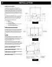
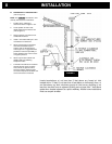
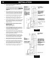
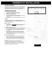
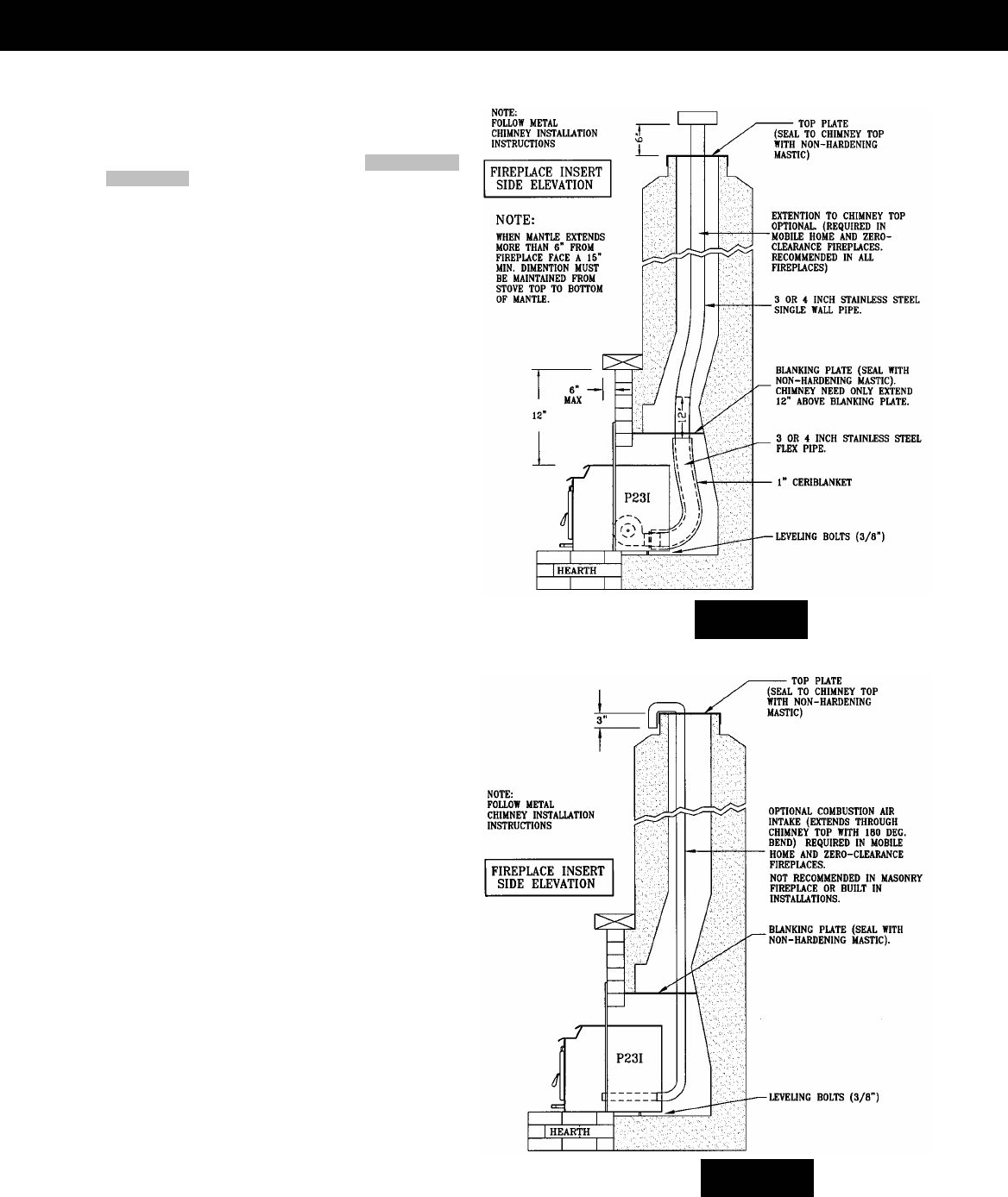
B. WHEN VENT PIPE EXTENDS TO CHIMNEY TOP
(Refer to Figures 16 and 17)
1. You will need a pipe length equal to the chimney height
(from hearth) plus 6 inches. If outside combustion air is to
be used, you will need a pipe length (see “COMBUSTION
AIR SUPPLY”) equal to the chimney height plus 12
inches.
2. Attach cerablanket wrap to that end of vent pipe that will
connect to the stove. Use 12-inch lengths of light gauge
metal wire (not included) or metallic tape (not included).
This is to protect interior components from excess heat.
3. Set the insert on the hearth and slide it in far enough to
attach the vent pipe (and combustion pipe if used).
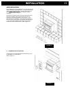
4. Attach flashing (refer to Figure 15), route power cord out
the side nearest a 120V receptacle. Slide in insert.
5. Measure and build chimney top. Cut out hole for vent pipe
(and combustion air intake pipe, if used). Install and seal
with a non-hardening mastic to prevent water leakage.
Install the vent cap.
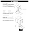
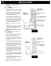
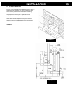
C. WHEN VENT PIPE EXTENDS THROUGH CHIMNEY
BLANKING PLATE
(Masonry Fireplaces Only)
(Refer to Figures 16 and 17)
1. You will need a pipe length that extends 12” above the
blanking plate. NOTE: This installation is optional but not
recommended. Outside combustion air cannot be drawn
from the chimney cavity in this installation.
2. Attach cerablanket wrap to that end of vent pipe that will
connect to the stove. Use 12-inch lengths of light gauge
metal wire (not included) or metallic tape. This is to protect
interior components from excess heat.
3. Measure and build blanking plate. Cut out hole for vent
pipe (and combustion air intake pipe, if used). Install and
carefully seal blanking plate with non-hardening mastic.
Failure to properly seal may result in smoke spillage.
4. Slide vent pipe (and intake pipe if used) up through the
blanking plate hole, leaving enough to pull back down.
5. Set the insert on the hearth, adjust the leveling bolts on
the rear sides, and slide it in far enough to attach the vent
pipe (and combustion air pipe if used). Be sure to seal
where the pipe passes through the blanking plate.
6. Attach flashing (refer to Figure 15), route power cord out
the side nearest a 120V receptacle. Slide in insert.
FIGURE 16
IN
S
TALLATI
O
N12
FIGURE 17