


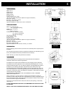
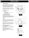
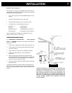
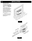
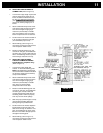
COMBUSTION AIR SUPPLY
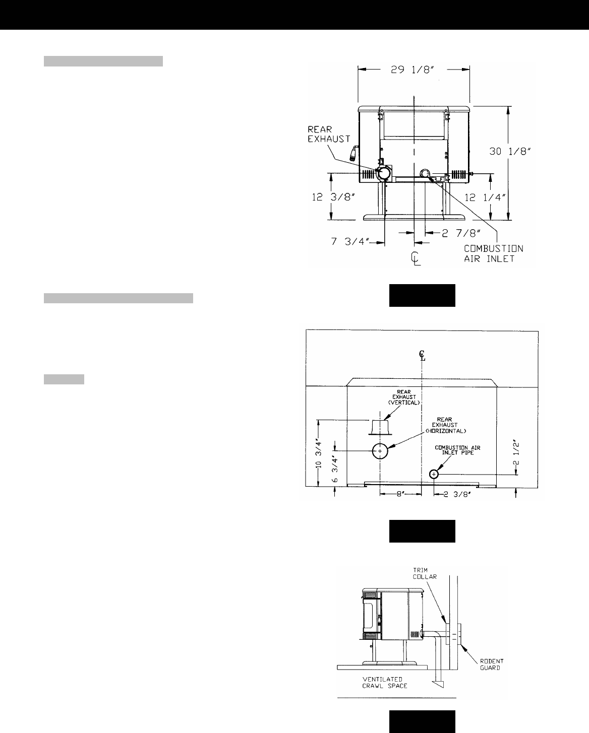
For a mobile home installation the stove must be connected to an
outside source of combustion air. A 2” inside diameter metallic pipe,
either flexible or rigid, may be attached to the inlet at the stove’s
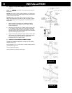
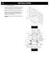
rear (refer to figures 5 & 6). A rodent guard (minimum ¼” wire
mesh)/wind hood must be used at the terminus (refer to figure 7).
All connections must be secured and airtight by either using the
appropriately sized hose clamp and/or UL-181-AP foil tape.
For mobile home installations only: 2” inside diameter pipe may
be used for the first 5 feet of combustion air supply run. From 5 to
10 feet use 2 ¾” inside diameter pipe. No combustion air supply
may exceed 10 feet.
Sources of Outside Combustion Air
a. In fireplaces
• Chimney top.
• Ash clean out door.
b. For freestanding installations
• A hole in floor near stove rear terminating only in a
ventilated crawl space.
• A hole in the wall behind the stove.
WHEN OUTSIDE AIR IS NOT USED
If outside air is not used, it is important that combustion air is easily
available to the air inlet. A closeable outside air register can be
used in tightly insulated homes. In insert installations, flashing vents
should not be restricted. The flashing should not necessarily seal
the fireplace face.
VENTING
The Breckwell P2000 is certified for use with listed TYPE L-Vent, 3”
or 4” diameter in size. The stove was tested with Simpson Duravent
brand. Class “A” chimney is not required. Refer to the instructions
provided by the vent manufacturer, especially when passing
through a wall, ceiling or roof.
This is a pressurized exhaust system. We suggest sealing all vent
connector joints with 500°F (260°C) RTV silicone sealant to ensure
consistent performance and to avoid smoke spillage. We also
suggest that all horizontal connector joints be sealed with UL-181-
AP foil tape.
FOLLOW L-VENT CHIMNEY MANUFACTURER’S
INSTALLATION INSTRUCTIONS.
DO NOT CONNECT THIS UNIT TO A CHIMNEY FLUE SERVING
ANOTHER APPLIANCE.
DO NOT INSTALL A FLUE DAMPER IN THE EXHAUST
VENTING SYSTEM OF THIS UNIT.
INSTALL VENT AT CLEARANCES SPECIFIED BY THE VENT
MANUFACTURER.
IN
S
TALLATI
O
N
6
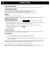
REAR VIEW P2000FS
FIGURE 5
REAR VIEW P2000I
FIGURE 6
FIGURE 7