


The following test should be performed while the pilot flame is on.
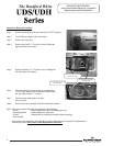
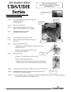
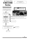
Step 1. Turn knob to pilot position and depress.
Step 2. Continue pressing knob and remove red (+) thermopile wire from the red wire leading from the gas control.
Also remove white (-) thermopile wire from the gas control.
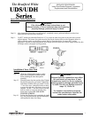
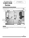
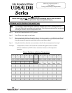
Step 3. Using a multimeter capable of measuring millivolts, connect the positive side of the multimeter to the
red (+) thermopile wire connector. Connect the negative side of the multimeter to the white thermopile
connector.
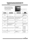
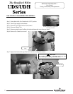
OPEN CIRCUIT THERMOPILE TESTING
Normal thermopile operation will be between 350mV - 850mV. If reading is less than 350mV, replacement of pilot
assembly is recommended following SERVICE PROCEDURE III.
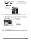
Step 4. If thermopile reading is between 350mV - 850mV, remove multimeter and reconnect red (+) thermopile wire
to red wire leading from the gas control. Reconnect white (-) thermopile wire negative (-) terminal on gas
control.
Step 5. Release Gas Control knob and turn to desired setting to resume normal operation.
SERVICE PROCEDURE II
Thermopile Testing and Replacement
9
Red gas control wire
Red (+) thermopile wire
White (-) thermopile wire
White (-) thermopile wire
Red (+) thermopile wire
The Bradford White
9