


Page 49
screws. Verify that both the left and right side inner doors are properly positioned and
sealed against the combustion chamber.
Step 8. Re-install the outer door.
Step 9. To resume operation, follow the instructions located on the water heater
lighting instruction label. Or, use the lighting instructions located in the water heater
installation and operating manual.
ScreenLok
®
Flame Arrestor Cleaning Procedure
Step 1. Move the gas control power switch to the “OFF” position and unplug the
water heater from the wall outlet.
Step 2. Remove the outer door.
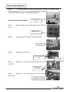
Step 3. Remove the right side inner door per the Inner Door Removal Procedure
on page 32.
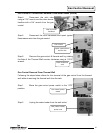
Step 4. Disconnect the pilot tube using a 7/16” wrench and the main burner
feedline with a 3/4” wrench from the gas control.
Step 5. Disconnect the spark igniter/flame sensor wire from gas control.
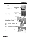
Step 6. Remove the burner assembly from the combustion chamber.
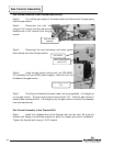
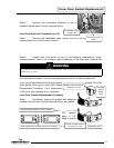
Step 7. Clean the ScreenLok
®
flame arrestor using a stiff brush, compressed air,
and/or a shop vacuum to remove any scale or other debris accumulation. Using a soft
brush, clear jacket openings from any dirt, dust, restrictions, or other obstructions.
Step 8. Remove any debris from the burner assembly following the Burner
Cleaning Procedure on page 15.
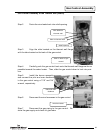
Step 9. Re-install the burner assembly.
Step 10. Reconnect the main and pilot tubing and spark igniter wire to the gas
control.
Step 11. Re-install the inner door per the Inner Door Installation with Gasket Pro-
cedure on page 34.
Step 12. To resume operation, follow the instructions located on the water heater
lighting instruction label. Or, use the lighting instructions located in the water heater
installation and operating manual.
Arrestor Cleaning
49