


36
Troubleshooting – Electrical
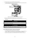
There are a number of (live) tests that are required when fault finding this product. Extreme care should
be used at all times to avoid contact with energized components inside the water heater. Only trained
and qualified service technicians should attempt to repair this product. Before checking for resistance
readings, disconnect the power source to the unit and isolate the item from the circuit (unplug it).
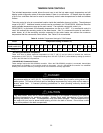
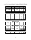
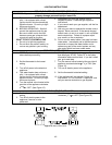
Table 11. (SV1, SV2, SV3, SV4, and POV) Gas Valve and Modulating Solenoids (Set Meter Above 2k).
Wire Color Voltage Resistance
Connector
No.
Pin
Nos.
(SV0) Pink-Black 11-13 VDC 37-43 ohms B5 7-8
(SV1) Blue-Black 11-13 VDC 37-43 ohms B6 6-7
(SV2) Yellow-Black 11-13 VDC 37-43 ohms B7 5-7
(SV3) Red-Black 11-13 VDC 37-43 ohms B3 4-7
(SV4) Orange-Black 11-13 VDC 37-43 ohms B4 3-7
(POV) Orange-Orange 2-15 VDC 67-81 ohms B2 10-11
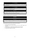
Table 12. (M) Water Flow Control Device Servo.
Wire Color Voltage Resistance
Connector
No.
Pin
Nos.
Red or Pink-Orange 5-7 VDC n/a G2
3 or 4-
8
Blue or White-
Orange
5-7 VDC n/a G2
1 or 2-
8
Red-Pink n/a 30-50 ohms G2 3-4
Blue-White n/a 30-50 ohms G2 1-2
Gray-Yellow 0-6 VDC n/a G2 7-5
Gray-Brown 0-6 VDC n/a G2 7-6
Note: The grey wire listed above turns to black at F connector on the PCB.
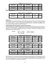
Table 13. (QS) Water Flow Sensor.
Wire Color Voltage Resistance
Connector
No.
Pin
Nos.
Black-Red 11-13 VDC n/a E5 1-3
Yellow-Black 4-7 VDC 1-1.4 Mega ohms E5 2-3
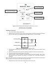
Table 14. By-pass Flow Control.
Wire Color Voltage Resistance
Connector
No.
Pin
Nos.
Brown-White
2-6 VDC (unit
in operating
mode)
15-35 ohms
G1 1-5
Orange-White G1 2-5
Yellow-White G1 3-5
Red-White -
Ground
G1 4-5
Table 15. (IG) Ignition System.
Wire Color Voltage Resistance
Connector
No.
Pin
Nos.
Grey-Grey 90-110 VAC n/a D1 1-2