


6
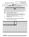
Thermistor Wire Testing
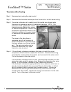
Step 1. Disconnect and unplug the solar control.
Step 2. Disconnect the thermistor twisted pair from the control or control sensor wiring.
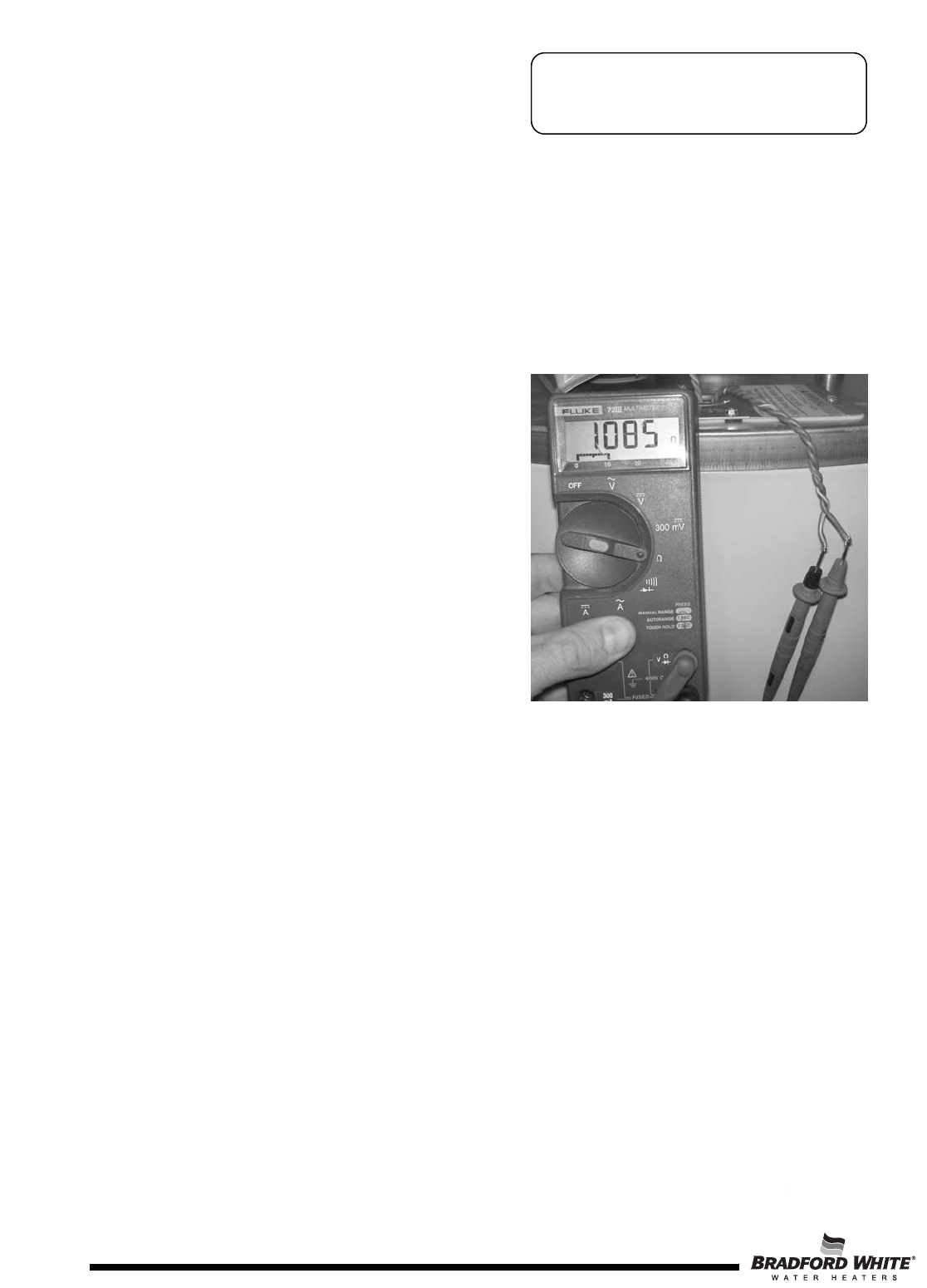
Step 3. Connect a multimeter set to read ohms to the twisted wire stripped ends.
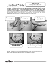
Determine the resistance value of the attached thermistor. NOTE: The
thermistor is field supplied and various
thermistors have different ohm values
for different temperatures. Refer to the
temperature specification sheet for the
thermistor installed on the water heater
to determine if the resistance value is
correct.
The image to the side shows a
resistance value for a thermistor at
ambient temperature connected under
the lower access cover (brown twisted
pair). The same procedure can be
followed to determine if the upper
thermistor value is correct.
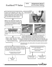
Step 4. If the multimeter indicates a resistance that does not match the actual
temperature of the thermistor, replace the thermistor. Reconnect the wiring,
verify that the new thermistor does match, and reconnect to the solar control.
Turn on the power to the solar control.
If the multimeter indicates a short or open, disconnect the thermistor from the
connection made under the access cover. Measure the thermistor ohm value
directly. If the multimeter indicates an open, replace the thermistor.
If the multimeter indicates an appropriate ohm value, determine which wire is
open by measuring directly from one end of the wire to the other, or if short;
verify by measuring both wire ends from the same location. If the wiring
cannot be fixed, the wiring for the thermistor may have to be ran on the
outside of the water heater. Replace the wiring, and reconnect it to the solar
control. Turn on the power to the solar control.
EcoStor2™ Solar
ST-I Thermistor Wiring
Test Procedure
6