


Page 21
Pilot Inspection, Testing, and Replacement (cont’d)
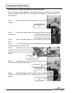
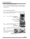
Step 12. Visually inspect the spark igniter/flame sense electrode for deterioration.
Replace the pilot assembly, if necessary. The electrode should not be in contact with
pilot hood. If it is in contact with the pilot hood, carefully adjust electrode to a gap
distance of 3/32" from the pilot hood.
Step 13. Visually inspect the spark igniter/flame sense electrode for oxidation
build-up. Carefully clean any oxidation using very fine emery cloth.
Step 14. Visually inspect the pilot tubing for kinks or cracks. If damage is found,
replace the pilot assembly.
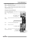
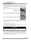
Step 15. Inspect the pilot tubing and pilot orifice for blockages:
a) Remove ferrule nut from the bottom of the pilot
assembly using a 7/16" wrench.
b) Remove the pilot tube and pilot orifice.
c) Inspect the pilot tubing and pilot orifice for
blockages. Clean or replace, as necessary.
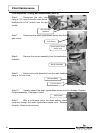
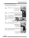
Step 16. Re-assemble the pilot assembly and install it on the main feedline. Re-
install the burner assembly into the combustion chamber. Restore the gas supply and
check for gas leaks.
Step 17. To resume operation, follow the instructions located on the water heater
lighting instruction label. Or, use the lighting instructions located in the water heater
Installation and Operation manual.
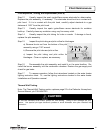
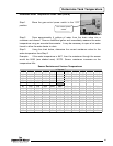
Thermal Well Testing
Note: The Thermal Well Testing section replaces page 22 in the Defender Atmospheric
Service Manual, p/n 238-44943-00.
Pilot Maintenance
CAUTION
Do not use standard multi-meter probes for this testing. Doing so will damage the con-
nector. Use special pin type electronic probes or small diameter wire pins inserted into
connector.
21