


Page 28
Flammable Vapor Sensor Testing (cont’d)
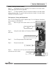
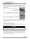
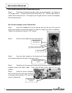
Step 3. Using a multi-meter set to the ohms setting, measure
the resistance of the flammable vapor sensor and resettable
thermal switch. The resistance must be between 3,000 and 48,000
ohms. If the resistance is out of this range, verify that the
resettable thermal switch has not been tripped. If it hasn’t, replace
the flammable vapor sensor.
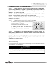
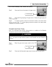
120 VAC Circuit Trace
Note: The 120 VAC Circuit Trace section is in addition to the Defender Atmospheric
service manual, p/n 238-44943-00.
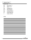
Step 1. Verify 120VAC and proper polarity are at the wall outlet.
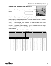
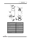
Step 2. With the water heater plugged in and the gas control power switch in the
“ON” position, verify LED status.
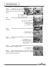
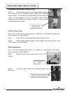
Relay Replacement
Note: The Relay Replacement section is in addition to the Defender Atmospheric
service manual, p/n 238-44943-00.
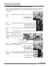
Step 1. Move the gas control power switch to the “OFF”
position.
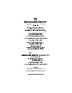
Step 2. Unplug the water heater and Accessory Module from the
wall outlet.
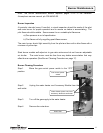
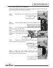
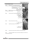
Flammable Vapor Sensor Testing
F
lammable vapor
sensor harness
Gas control power
switch
Water heater power cord and
Accessory Module transformer
28