


PDX SERVICE PROCEDURE VI
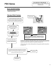
Gas Control/Thermal Well Testing and
Replacement
PDX Series
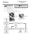
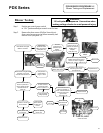
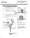
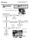
Thermal Well Testing
Thermal well testing
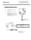
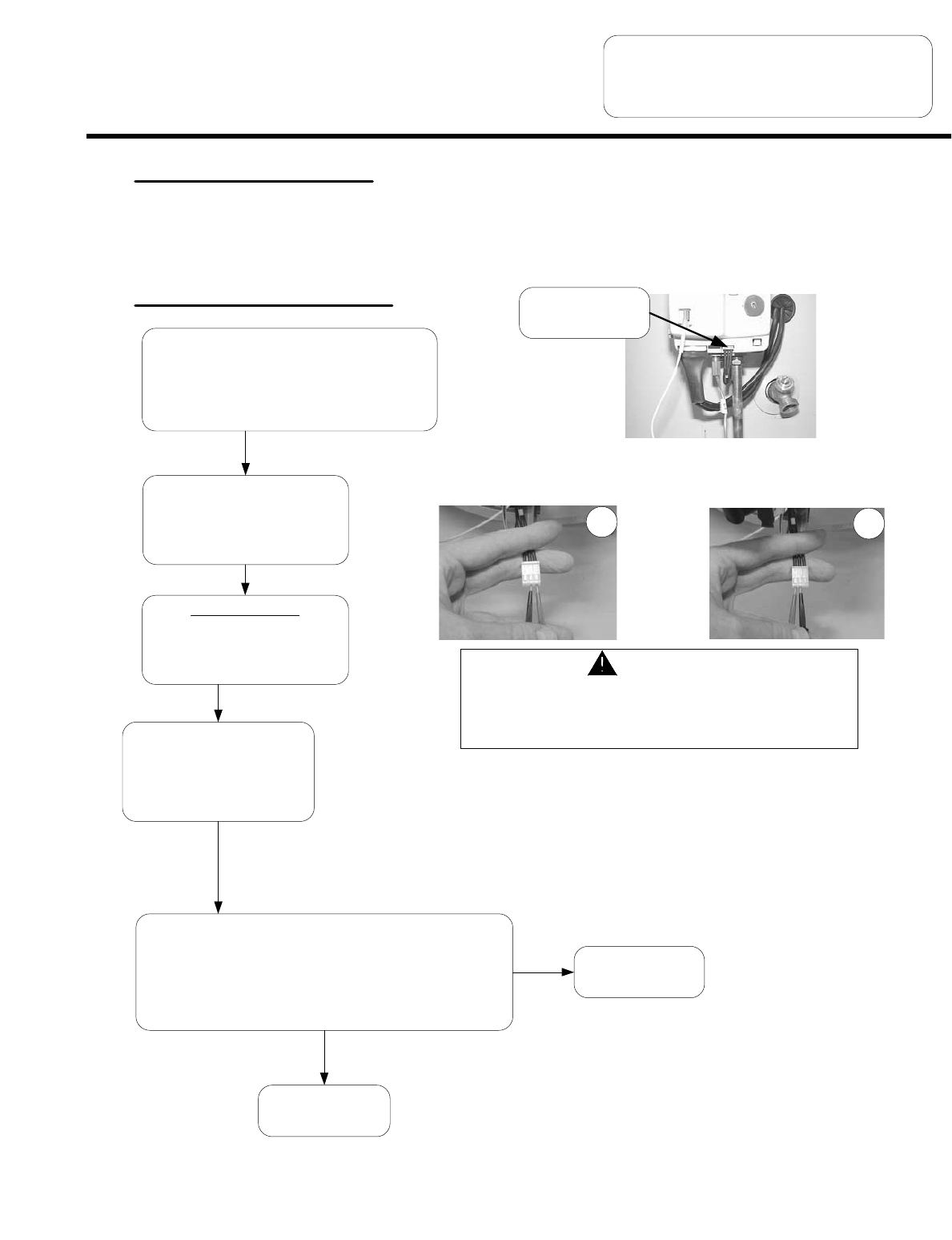
Position gas control power switch to
the “OFF” position and disconnect
thermal well harness from gas
control.
N
Y
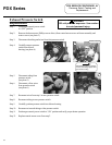
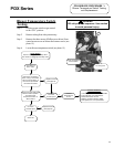
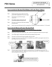
Using a multi-meter set to the ohms setting, insert one meter probe (see caution)
into center wire position of thermal well connector, insert the second probe (see
caution) into either of the outside wire positions (see photo 23).
Alternate the probe on the outside position to the opposite outside wire position
(see photo 24).
Replace thermal well
(see page 27)
Using a multi-meter set to the
Ohms setting, determine the
resistance of thermal well sensor
(see caution photos 23 & 24)
Disconnect thermal
well wire harness
19
20
Replace gas control
(see page 27)
Page 25
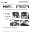
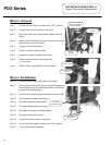
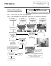
Gas Control Testing
See pages 27 & 28 for gas control
input & output testing.
Once the thermal well resistance values are known, the water
temperature must also be known to determine if the resistance
values are correct. See page 25 to obtain water temperature.
Are thermal well resistance values correct?
CAUTION
DO NOT use standard multimeter probes for this test.
Doing so will damage connector. Use special pin type
electronic probes or small diameter wire pins inserted
into connector.
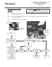
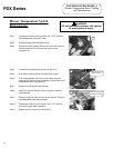
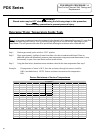
If Control has gone into TCO lockout due to
excessive tank temperature (four flash, 3 second
pause) reset control by rotating knob of temperature
control to the minimum setting for at least 6 seconds
before returning to desired temperature setting.
Observe heater operation. If control
continues to lockout due to
excessive tank temperature,
proceed to thermal well testing to
determine cause.
25