


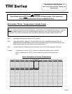
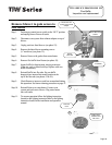

TTW SERVICE PROCEDURE VIII
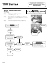
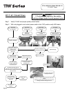
Safety Circuit Voltage Trace
Safety Circuit Voltage
Trace
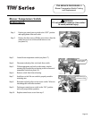
WARNING
115 volt potential exposure. Use caution
making voltage checks to avoid personal injury.
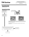
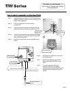
Position gas control switch to the “ON”
position and adjust thermostat dial to call
for heat, Is there 10 to 13 VAC between
red wire leading to blower temperature
switch and green ground wire?
Blower must be running during this
voltage check.
(see photo 27)
Red wire leading to
blower temp. switch
Green ground wire
27
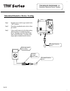
Yellow wire
leading from
pressure switch
Y
Is there 10 to 13 VAC between yellow
wire leading from pressure switch and
green ground wire?
(see photo 27)
Do you hear or can you
see the igniter sparking?
Y
Y
Is LED on gas valve flashing
the “heartbeat” code
(alternating bright/dim)
N
Safety circuit
voltage is OK.
No voltage from gas control,
call for technical support.
Y
NOTE: This procedure assumes a cool tank.
Verify 115VAC to gas
control (see page 30)
Is there continuity
through blower
temperature switch?
(see page 22)
Y
Check for loose or
broken wire
connection at switch
terminals
N
N
Determine cause of blower
temperature switch
activation and correct.
Check igniter/sensor
(see page 17)
is igniter/sensor OK?
If burner does not light,
observe LED flash code
on gas valve and refer to
troubleshooting section
on page 13
N
N
Page 29
26
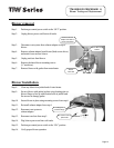
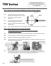
Remove three screws (Phillips Screw driver) from control access
cover on blower and remove cover (see photo 26).
Faulty cord set or
gas control.
Y
Correct igniter/
sensor problem.
pg29.pdf 1pg29.pdf 1 3/28/06 11:49:25 AM3/28/06 11:49:25 AM
Page 29