


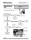
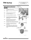
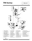
Inner Door Removal Procedure
Step 1. Position gas control power switch to the “OFF” position.
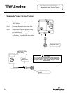
Step 2. Remove outer jacket burner access door
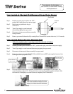
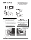
Step 3. Inner Door Removal.
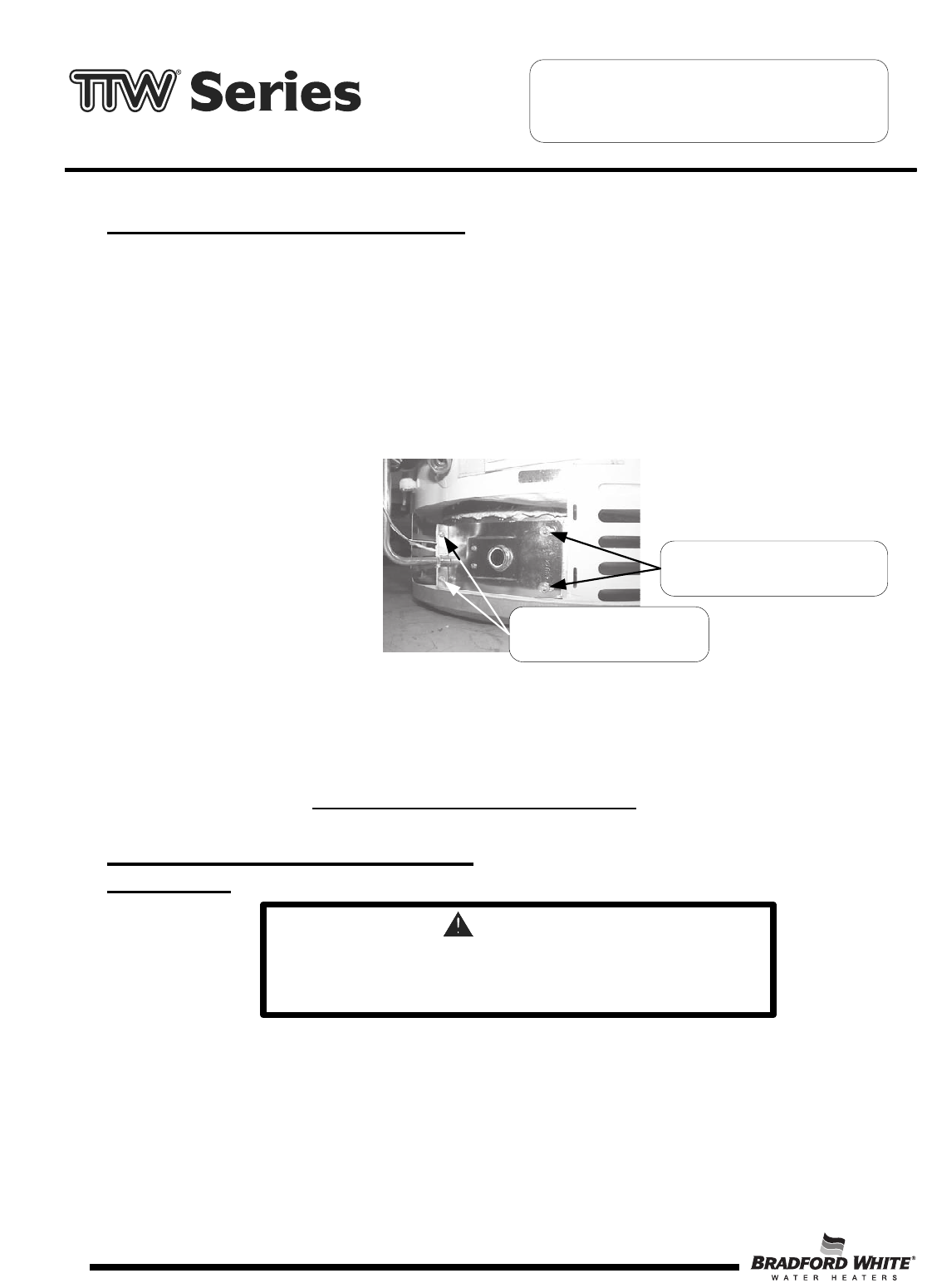
a) Remove (2) 1/4" hex drive screws from right side inner door.
b) Remove (2) 1/4" drive screws from flange section of inner door.
c) Remove (2) 1/4" drive screws from left side inner door.
d) Remove inner door and inspect per step 4.
¼" Hex Drive Screws
Right and Left Side Inner Door.
¼" Hex Drive Screws at
Flange Area of Inner Door
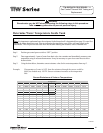
Step 4. Fully inspect inner door gaskets for the following:
>Tears >Other imperfections that will inhibit proper seal
>Missing Material >Gasket adhesion to inner door
>Cracks >Material left on combustion chamber (around opening)
>Dirt or debris
If the gasket is not effected by any of the above, gasket replacement is not required. If replacement is
required,
proceed to Inner Door Gasket Replacement Procedure.
Inner Door Gasket Replacement
Procedure.
WARNING
If the information in these instructions is not
followed exactly, a fire or explosion may result causing
property damage, personal injury or death.
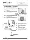
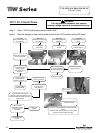
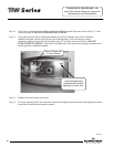
Step 5. After inspection of inner door as noted in step 4, completely remove gasket and adhesive residue from right
and left side inner doors as needed.
Step 6. Use RTV sealant (recommended bead size 1/8") to secure the inner door gasket to the inner door sections
(right & left). Refer to illustration on next page for proper application. Note the overlap configuration in the
flange area of the inner door. Set the flange section first, this will help to achieve the proper over lap position.
TTW SERVICE PROCEDURE XIII
Inner Door/Gasket Removal, Inspection
Replacement and Reinstallation
Page 34
Page 34
34