


RESETT
ABLE THERMAL SWITCH REPLA
CEMENT
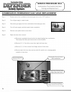
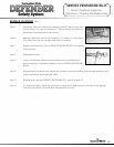
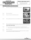
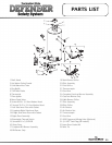
Step 1. Rotate knob of combination thermostat gas valve to the off position.
Step 2. Remove outer jacket door.
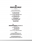
Step 3. Disconnect wire leads from resettable thermal switch.
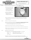
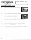
Step 4. Remove resettable thermal switch from inner door (Phillips screw driver).
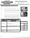
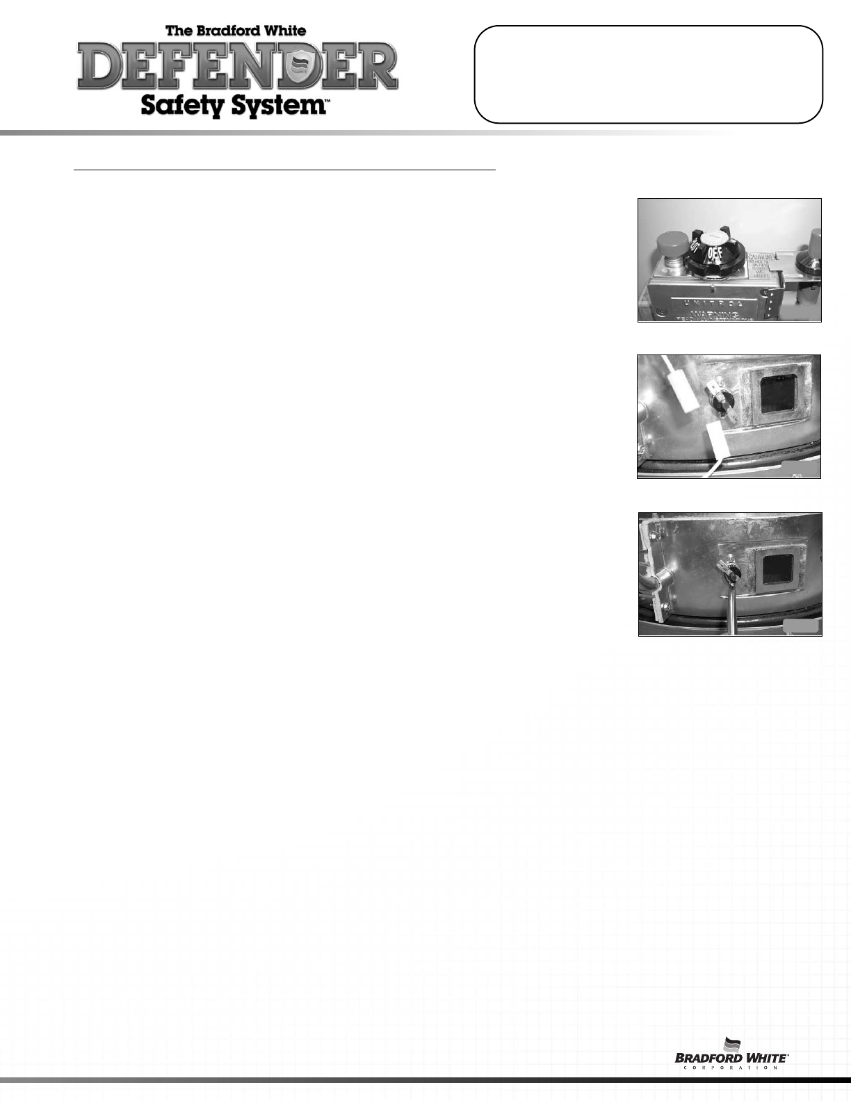
Step 5. Place new resettable thermal switch in place. Be sure contact surface of resettable thermal switch and
inner door are free of any debris. Secure resettable thermal switch into place using screws from step 4.
DO NOT OVER TIGHTEN SCREWS.
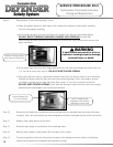
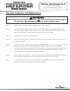
Step 6. Reconnect wire leads from combination thermostat/gas valve to resettable thermal switch.
Note: wire termination are interchangeable with either resettable thermal switch connection.
Step 7. Replace outer jacket door.
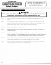
Step 8. To resume operation follow the instructions located on the lighting instruction label or the lighting
instruction located in the installation and operation manual.
SERVICE PROCEDURE RG-VII
Resettable Thermal Switch
Testing and Replacement
21