


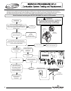
Blower Replacement Procedure
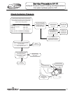
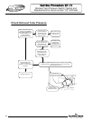
Step 5. Disconnect wire harness from blower.
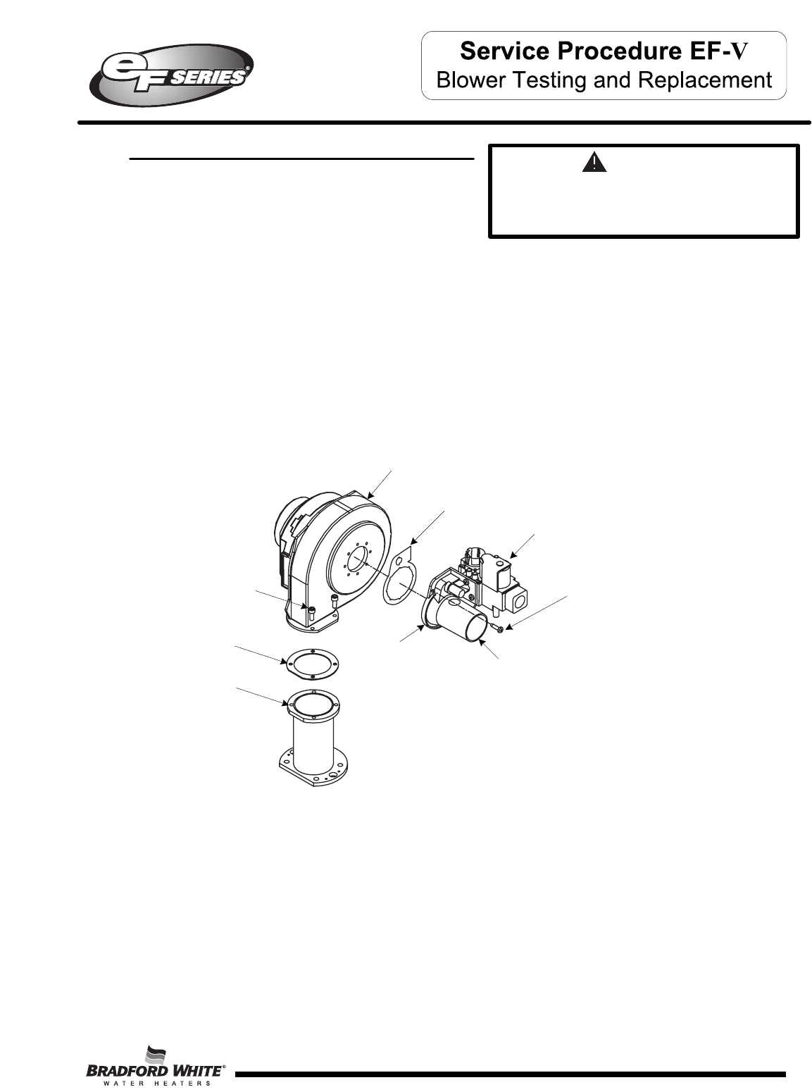
Step 6. Disconnect intake vent and gas supply from gas valve assembly.
Step 7. Remove the 2 gas valve mounting screws (Torx bit) located at the
11:00 O-clock & 5:00 O-clock position on the venturi mounting flange.
Step 8. Remove The 4 blower flange mounting screws (5/32 Allen wrench) and remove blower
from transition flange.
Step 9. Remove any residual gasket material
from venturi mounting flange and transition flange.
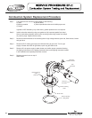
Step 10. Install new blower with new gasket
provided. Secure blower in place using
screws from step 8.
Step 11. Reconnect gas valve assembly to blower
with new gasket provided. Secure gas
valve in place using screws from step 7.
Step 12. Reconnect intake vent and
gas line to gas valve assembly and
check for gas leaks repair any leaks found.
Step 13. Reconnect wire harness to blower assembly, restore 120 volt power supply & Gas supply
to water heater and confirm proper operation following the lighting instructions on the
lighting instruction label or the lighting instructions located in the installation and operating
instruction manual.
Step 14. Replace surround cover on top of
water heater.
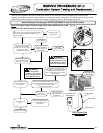
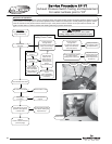
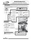
Step 1. Position main power switch to “OFF”.
Step 2. Disconnect (unplug) water heater from
120 volt power source.
Step 3. Turn off gas supply to water heater.
Step 4. Un-latch & remove surround cover from top of
heater.
WARNING
120 volt potential exposure. Isolate the
appliance and reconfirm power is
disconnected using a multi-meter.
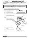
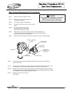
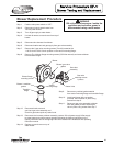
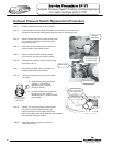
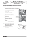
Gas valve
assembly
Blower / gas valve
gasket
Blower
Venturi
mounting flange
Gas valve
mounting screws
2 places.
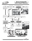
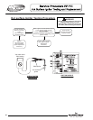
Blower / transition
gasket
Blower flange
mounting screws
Transition
flange
Venturi inlet
53
53